Multifunctional one-way cable clamp
A cable clamp, multi-functional technology, applied in the direction of circuits, electrical components, conductive connections, etc., can solve the problems of short service life, easy loosening of screws, uneven force, etc., to achieve convenient and safe use, stable and reliable connection, clip The effect of constant tension
- Summary
- Abstract
- Description
- Claims
- Application Information
AI Technical Summary
Problems solved by technology
Method used
Image
Examples
Embodiment 1
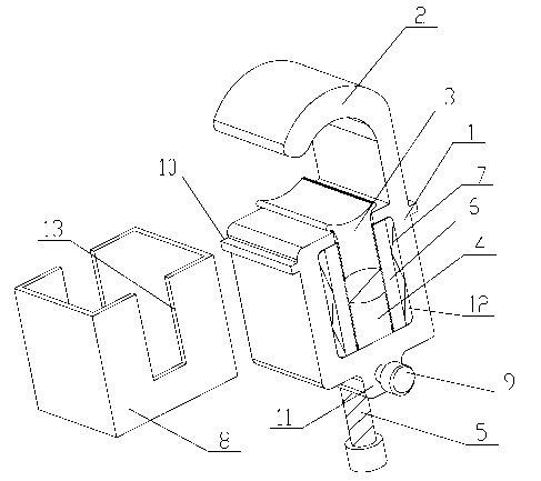
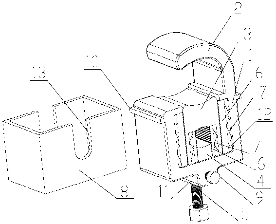
[0023] like figure 1 and figure 2 As shown, a multifunctional one-way cable clamp includes a clamp body 1, a groove 12 is provided in the clamp body 1, and a first movable chuck 3 that can move up and down is embedded in the groove 12 from top to bottom and the second movable chuck 4, the upper and lower ends of the first movable chuck 3 are provided with a structure for clamping, the upper end of the second movable chuck 4 is provided with a structure for clamping, and the top of the clamp body 1 is fixedly connected There is a static chuck 2 opposite to the first movable chuck 3, a bolt hole is provided under the clamp body 1, an adjusting bolt 5 passes through the bolt hole and is fixedly connected with the wire clamp body 1, and is connected with the second movable clamp The first 4 tops are connected. Wherein the static chuck 2 and the first moving chuck 3, the first moving chuck 3 and the second moving chuck 4 are the clamping parts, the static chuck 2 and the first m...
Embodiment 2
[0025] On the basis of embodiment 1, this embodiment has been improved as follows:
[0026] Wherein at least one side of the first movable chuck 3 is provided with a downwardly reversed anti-return sawtooth, and the outer side of the first movable chuck 3 is provided with an anti-loosening anti-reverse sawtooth sheet 6 that cooperates with it, at least A compression spring 7 is provided between the anti-loosening and anti-reversing sawtooth sheet 6 on one side and the clamp body 1, and the first movable chuck 3 and the anti-loosening and anti-reversing sawtooth sheet 6 are compressed by the compression spring 7. Wherein the compression spring 7 is a wave-shaped leaf spring or a columnar spring, and the columnar spring can be a cylindrical helical spring, preferably a leaf spring. The difference from Example 1 during disassembly is that the outer protective cover 8 needs to be disassembled first, the pressure spring 7 is taken out, the anti-loosening anti-reverse saw tooth piec...
Embodiment 3
[0028] On the basis of embodiment 1, this embodiment has been improved as follows:
[0029] Wherein at least one side of the second movable chuck 4 is provided with a downwardly reversed non-return sawtooth, and the outer side of the second movable chuck 4 is provided with an anti-loosening anti-reverse sawtooth sheet 6 that cooperates with it, at least A compression spring 7 is provided between the anti-loosening and anti-reversal sawtooth sheet 6 on one side and the clamp body 1, and the second movable chuck 4 and the anti-loosening and anti-reversal sawtooth sheet 6 are compressed by the compression spring 7. Wherein the compression spring 7 is a wave-shaped leaf spring or a columnar spring, and the columnar spring can be a cylindrical helical spring, preferably a leaf spring. The difference with embodiment 1 during disassembly is: the outer protective cover 8 needs to be dismantled first, the compression spring 7 is taken out, the anti-loosening anti-reverse saw tooth piec...
PUM
 Abstract
Description
Claims
Application Information
 - R&D Engineer
- R&D Manager
- IP Professional
- Industry Leading Data Capabilities
- Powerful AI technology
- Patent DNA Extraction
Browse by: Latest US Patents, China's latest patents, Technical Efficacy Thesaurus, Application Domain, Technology Topic, Popular Technical Reports.
© 2024 PatSnap. All rights reserved.Legal|Privacy policy|Modern Slavery Act Transparency Statement|Sitemap|About US| Contact US: help@patsnap.com


