
Bunch stranding machine

A technology of stranding machine and transmission motor, which is applied in the manufacture of wire harnesses, electrical components, circuits, etc., can solve problems such as low work efficiency and complex structure of stranding machines, and achieve high production efficiency, simple structure, and good stability

Active Publication Date: 2013-03-27
JIANGSU HANDING MACHINERY
View PDF2 Cites 11 Cited by
  • Summary
  • Abstract
  • Description
  • Claims
  • Application Information

AI Technical Summary

Problems solved by technology

[0004] The beam stranding machine in the prior art has a complex structure and low work efficiency, which is a technical problem in this field

Method used


Image

  • Bunch stranding machine
  • Bunch stranding machine

Examples


Embodiment Construction

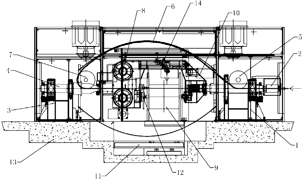
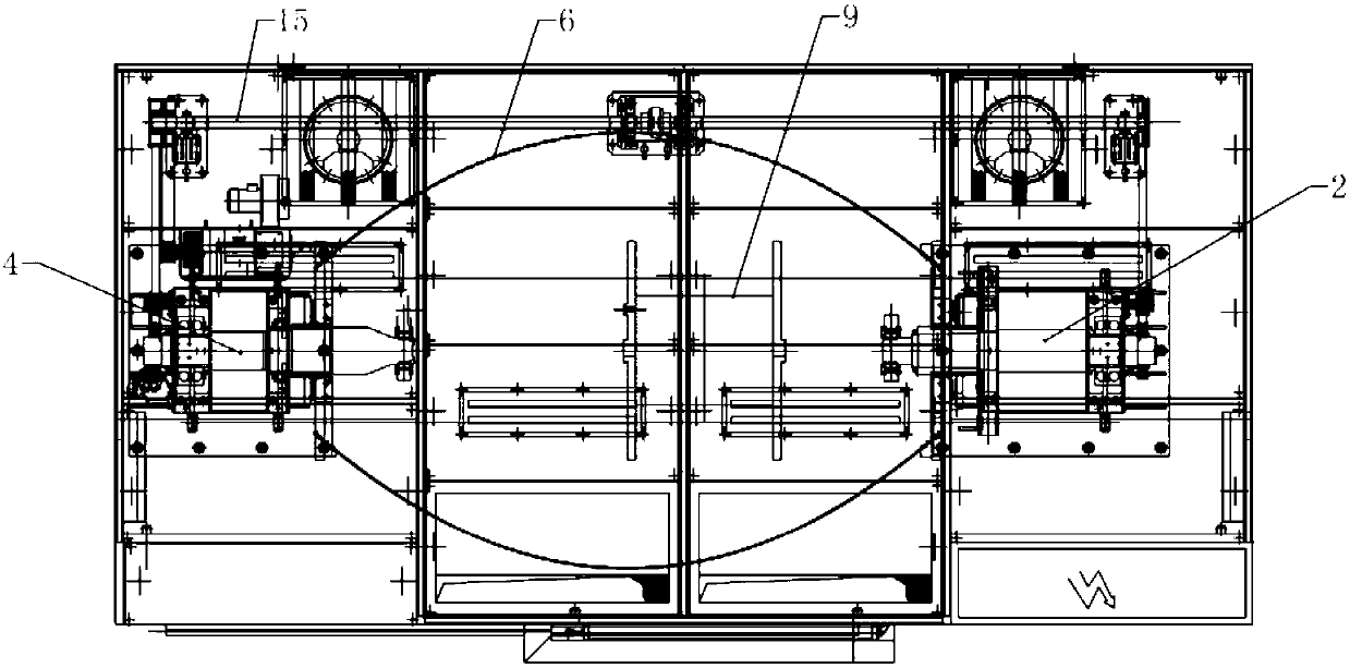
[0017] See figure 1 , the stranding machine of present embodiment comprises front and rear support 1,3 that is located on the base 13, front and rear support 1,3 bearings are respectively connected with coaxial line distribution and front rotating shaft 2, rear with central through hole. The shaft 4, the front shaft 2, and the rear shaft 4 are connected with a pair of bow straps 6 that bulge outwards and are symmetrically distributed. The pair of bow straps 6 are provided with bearings to connect between the front shaft 2 and the rear shaft 4. The cradle 10 of the pair of bow belts 6 is distributed with a plurality of lead wire guide wheels on the inner surface. The cradle 10 is provided with a winding reel 9 and a driving mechanism for driving the reel 9 to rotate, adjacent to the front The rear end of rotating shaft 2 and the front end of described rear rotating shaft 4 are respectively provided with front guide wheel 5, rear guide wheel 7, on described front rotating shaft ...


PUM


Abstract

The invention relates to a working method of a bunch stranding machine. The working method of the bunch stranding machine includes: when performing bunch stranding on a plurality of filiform cables, a transmission motor performs synchronous transmission on a front rotating shaft and a rear rotating shaft through a ground shaft and drives arch belts to rotate synchronously; and under the traction of a traction wheel, the filiform cables enter from the front end of a central through hole of the front rotating shaft, are output from a cable outlet hole of the front rotating shaft, sequentially bypass a front guiding wheel, lead guide wheels on the arch belt on one side and a rear guiding wheel to enter a cable inlet hole of the rear rotating shaft, then are output from the front end of a central through hole of the rear rotating shaft, and then sequentially pass by the traction wheel, a guiding wheel group on one side of the traction wheel and a flat cable mechanism to be wound on a cable spool in a rotating state. A curling motor is adopted to drive the cable spool to rotate through tip cone assembly; and after curling of the cable spool is finished, a transmission motor, the traction motor and the flat cable mechanism are controlled to be shut down, then a hydraulic cylinder enables a lifting table to rise to a spool discharging position, then the tip cone assembly is released, and the discharging of the cable spool can be finished.

Description

[0001] This application is a divisional application, the application number of the original application is 201110275581.6, the application date: 2011-9-16, the name of the invention: beam stranding machine and its working method. technical field [0002] A stranding machine for stranding multiple filamentary cables in the electric wire industry of the present invention, its main function is: an operating device for stranding or compressing two or more filamentary cables into bundles, Specifically, it is a working method of a beam stranding machine. Background technique [0003] In the field of cable production, it is necessary to use a stranding machine to twist a large number of conductor bundles to achieve different wire diameter specifications. [0004] The beam stranding machine in the prior art has complex structure and low working efficiency, which is a technical problem in this field. Contents of the invention [0005] The technical problem to be solved by the pres...

Claims


Application Information

Patent Timeline
IPC IPC(8): H01B13/012H01B13/02
Inventor 肖小勤
Owner JIANGSU HANDING MACHINERY
Learn More