
Electric screw press

A technology of electric screw and press, which is applied to the driving devices of presses, stamping machines, forging presses, etc. It can solve the problems of long slider length and small slider stroke, so as to increase forging energy and reduce contact Frictional resistance, the effect of accelerating the return speed

Inactive Publication Date: 2013-03-27
HUBEI NAFU GEARING MACHINERY +1
View PDF8 Cites 31 Cited by
  • Summary
  • Abstract
  • Description
  • Claims
  • Application Information

AI Technical Summary

Problems solved by technology

[0004] The invention provides an electric screw press, which solves the problems of long slider length and small slider stroke existing in the existing electric screw press, and is used for pressing clay bricks, refractory bricks and large height dimensions metal forging die forging

Method used


Image

  • Electric screw press
  • Electric screw press
  • Electric screw press

Examples


Embodiment Construction

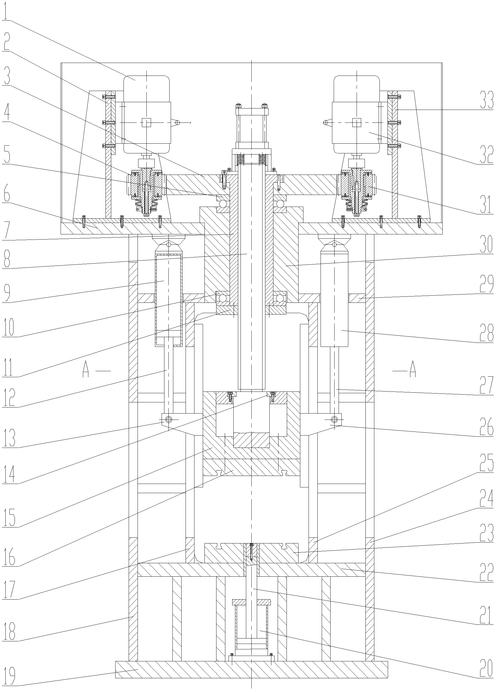
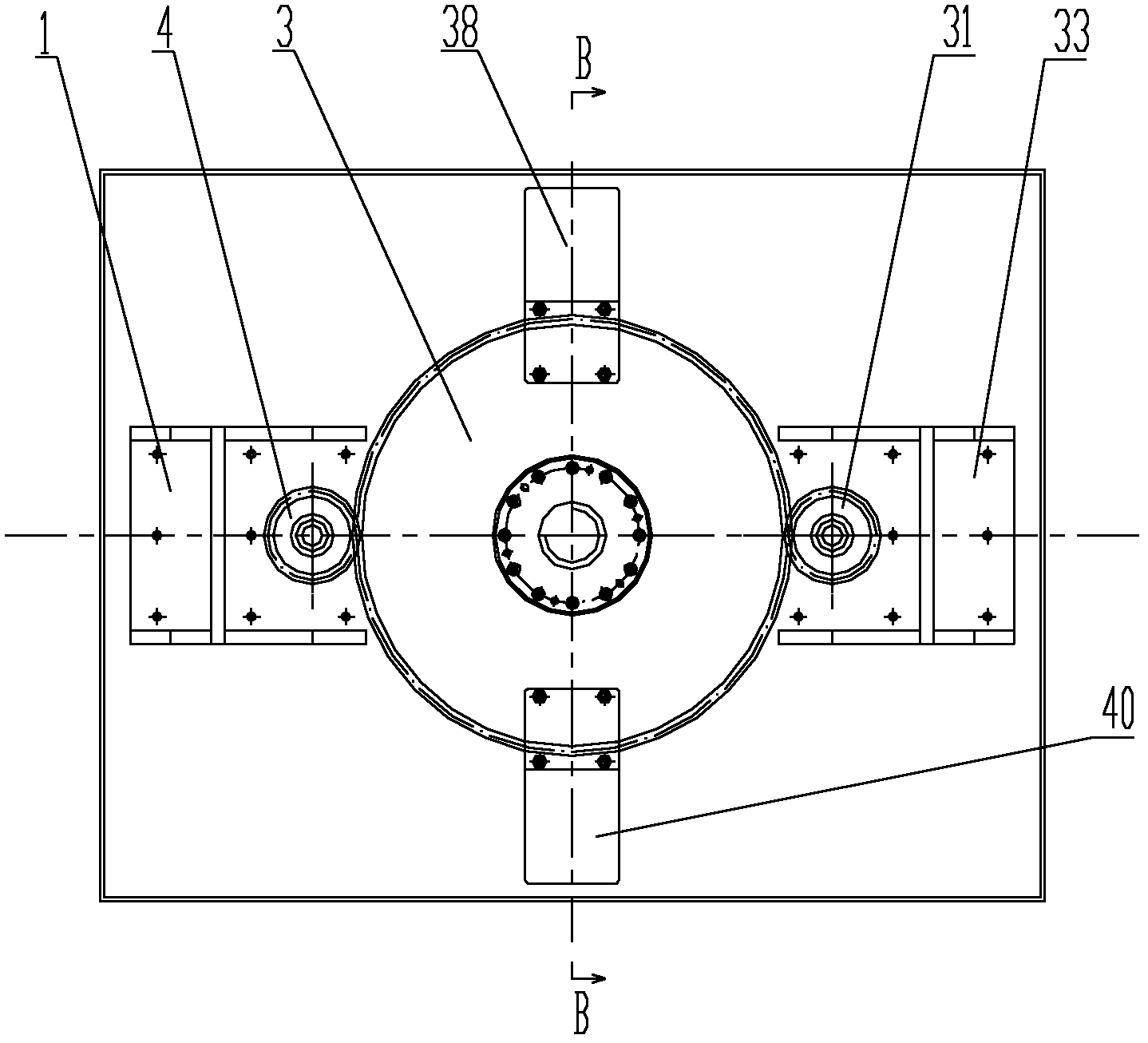
[0021] Such as Figure 1 ~ Figure 4 As shown, the embodiment of the present invention comprises upper beam top plate 6, left side plate 18, right side plate 24, lower beam bottom plate 19, bull gear 3, nut 7, screw rod 8, slider body 15, ejection cylinder 20, Left motor 1, right motor 32, front brake cylinder 38, rear brake cylinder 40;

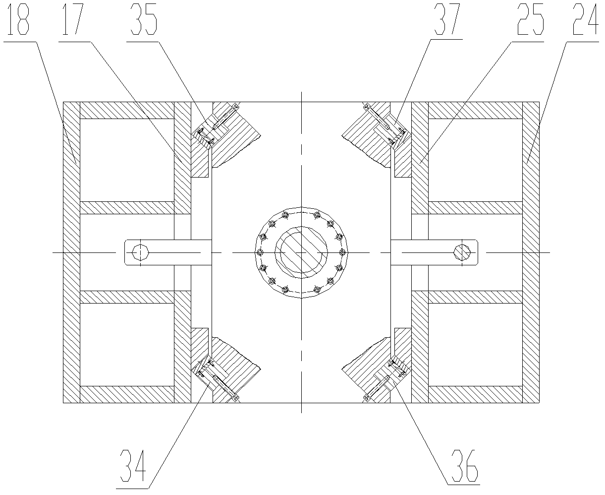
[0022] The fuselage is a frame structure, which is composed of an upper beam top plate 6, a left side plate 18, a right side plate 24, and a lower beam bottom plate 19. An upper plate 29 and a lower plate 22 are respectively fixed on the upper and lower parts of the fuselage. , the left inner panel 17 and the right inner panel 25 are fixed between the upper panel 29 and the lower panel 22, the left front guide rail 34 and the left rear guide rail 35 are fixed on the left inner panel 17, and the right front guide rail 36 and the right front guide rail 36 are fixed on the right inner panel 25. rear rail 37;

[0023] The central part of the up...


PUM


Abstract

The invention discloses an electric screw press, belongs to forging forming equipment, solves the problem that a slider is long and has a small travel in the conventional electric screw press, and is used for producing clay bricks, refractory bricks, common die forgings and precision die forgings. The electric screw press comprises a press body, a main gear, a nut, a screw, a slider body, an ejection cylinder, a left motor, a right motor, a front brake cylinder and a rear brake cylinder; and a left piston cylinder and a right piston cylinder which are bilaterally symmetrical are fixed in the press body. The nut and the main gear are tightened and rotate under the drive of the left and right motors; and the screw and the slider body are connected into a whole and driven by the nut to linearly move vertically, the screw can extend out of the upper end face of the main gear, the length of the slider body is consistent with or is even less than the height of a slider of a friction screw press with the same nominal pressure and body dimensions, the travel of the slider body can be increased by more than 100mm, the hammering energy of the slider body is correspondingly increased, and the application range can be widened obviously.

Description

technical field [0001] The invention belongs to forging and pressing forming equipment, which is used for the production of clay bricks and refractory bricks, common die forgings and precision die forgings. Background technique [0002] There are existing electric screw presses at home and abroad. The motor is driven by a first-stage gear, that is, a pinion is installed on the motor shaft. The motor drives the flywheel and the screw connected with the flywheel through the pinion to rotate. The nut on the block makes the slider move up and down in a straight line to realize the forging function; the flywheel can be driven by multiple motors through the pinion at the same time, so the specification can be made very large. At present, the world's largest tonnage reaches 320MN, which is far larger than other die Tonnage of forging equipment. See Xiong Xiaohong et al., "CNC Electric Screw Press", Forging Technology, 2007, vol.32, NO.5: 110-113; Zhang Yuanliang et al., "Research ...

Claims


Application Information

Patent Timeline
Patent Type & Authority Applications(China)
IPC IPC(8): B30B1/18B21J9/18
CPCB30B15/041B30B1/18
Inventor 夏巨谌胡国安吴彤汪丽邹树林
Owner HUBEI NAFU GEARING MACHINERY
Learn More