
Cover plate structure

A cover plate and plate technology, which is applied in the field of cover plate structure, can solve the problems of user trouble, lack of gripping force, interruption of electrical connection of the connector 20, etc.

Inactive Publication Date: 2013-03-20
INVENTEC CORP
View PDF5 Cites 2 Cited by
  • Summary
  • Abstract
  • Description
  • Claims
  • Application Information

AI Technical Summary

Problems solved by technology

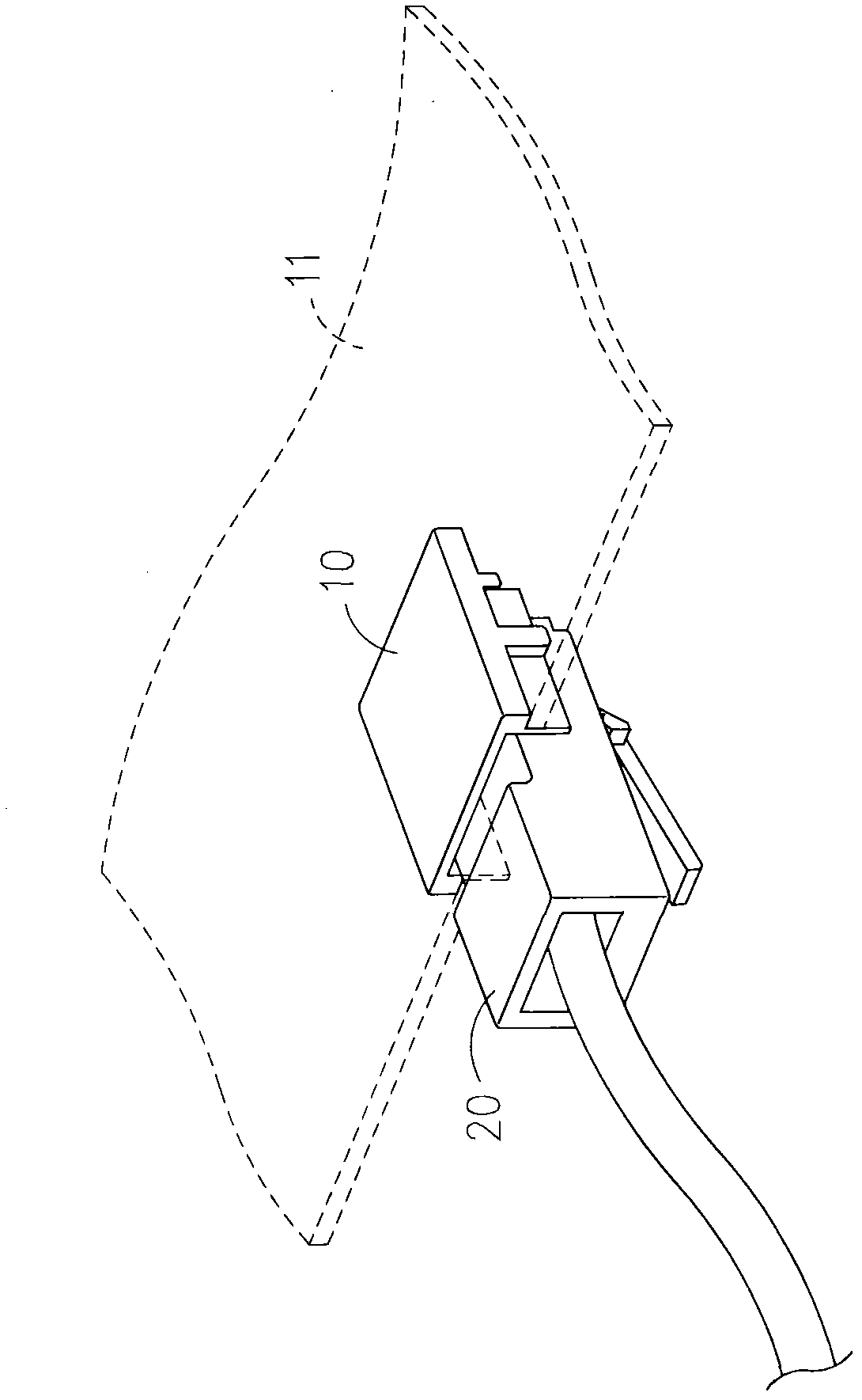
[0003] However, the disadvantage of the above structure is that the connector 20 is simply inserted into the thin connection base 10, and there is almost no gripping force between the thin connection base 10 and the connector 20, so the connector 20 is very easy to be connected by a thin connection. The seat 10 is loose and causes the electrical connection to be interrupted, causing great trouble to the user

Method used


Image

  • Cover plate structure
  • Cover plate structure
  • Cover plate structure

Examples


Embodiment Construction

[0029] The technical means and functions used by the present invention to achieve the purpose will be described below with reference to the attached drawings, and the embodiments listed in the following drawings are only for auxiliary explanation, so as to facilitate the examiner's understanding, but the technical means of the present invention It is not limited to the figures listed.

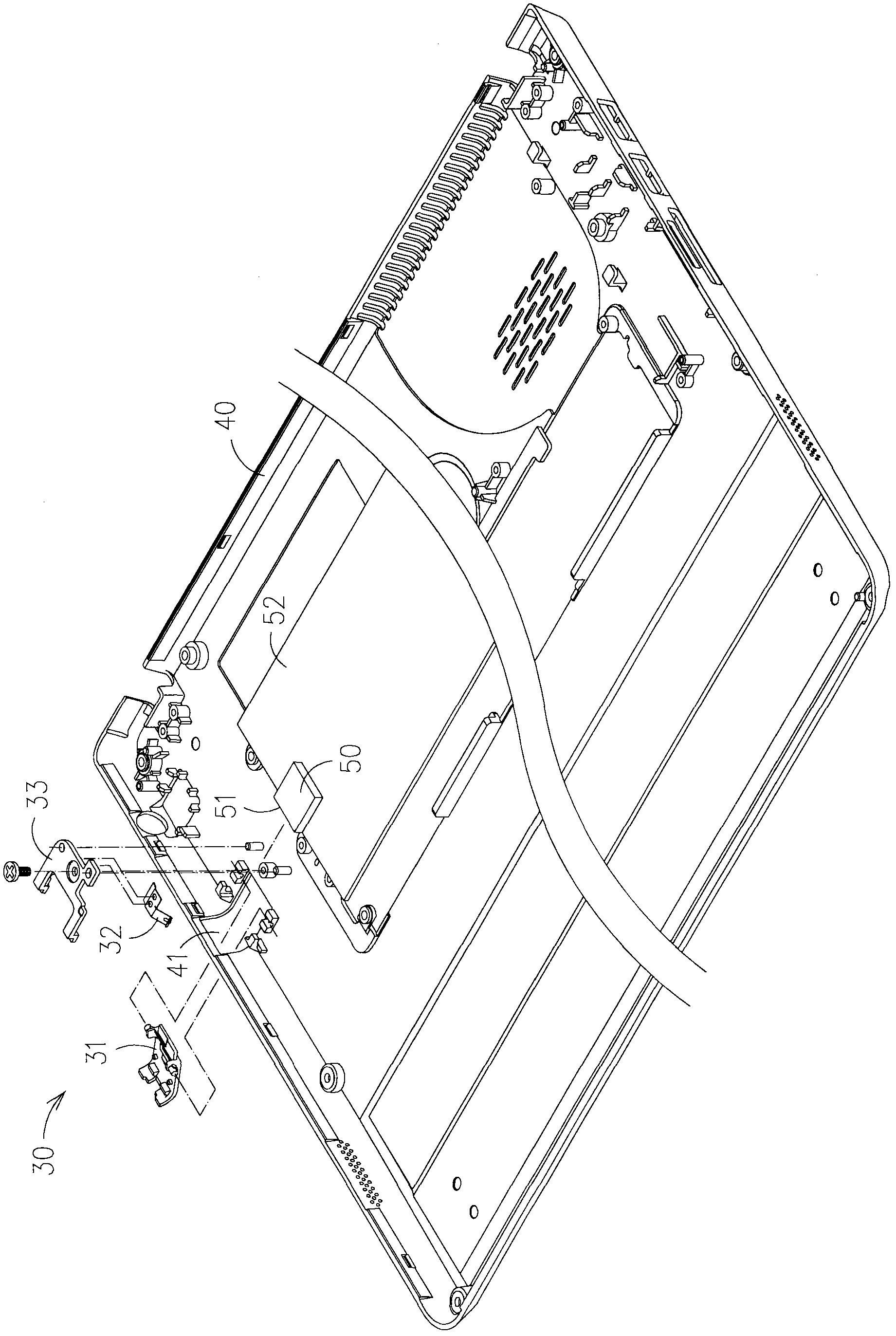
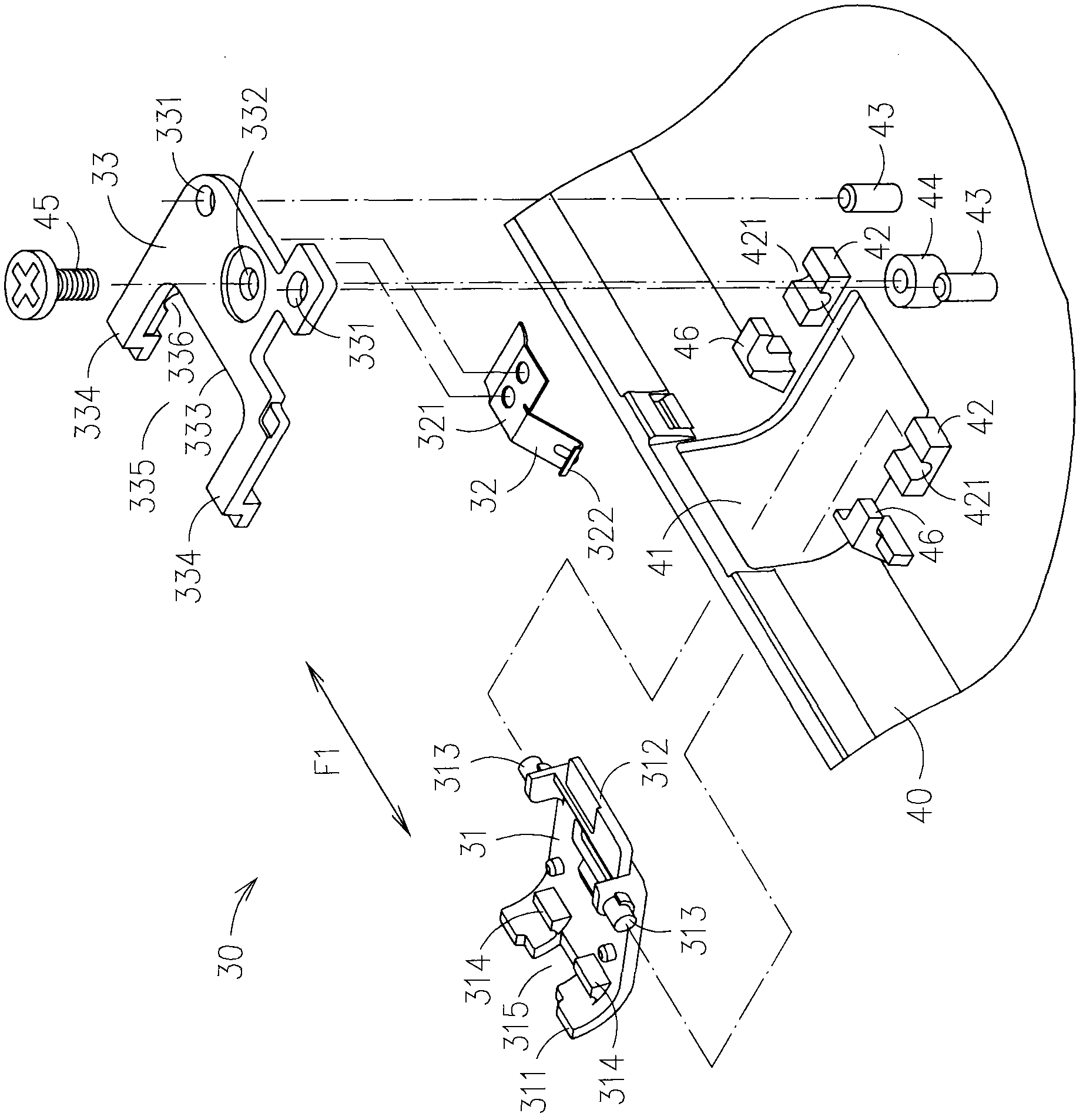
[0030] see Figure 2 to Figure 4 As shown, the cover plate structure 30 provided by the present invention is arranged on a casing 40, an opening 41 is provided in the casing 40, a connecting seat 50 is arranged in the casing 40, and the connecting seat 50 is arranged on a circuit board 52 Above, the connecting base 50 has a plugging end portion 51 , the plugging end portion 51 is embedded in the opening portion 41 from the housing 40 and exposed to the opening portion 41 . The opening 41 can provide a connector (not shown in the figure) to be inserted into the housing 40 from the outside of th...


PUM


Abstract

A cover plate structure is arranged on a shell which is provided with an opening portion. A connection seat is arranged in the shell. The connection seat is provided with an insertion end portion which is arranged in the opening portion in an exposed mode. The cover plate structure comprises a body and an elastic part. The body is connected with the shell in a pivot mode. A pivot is axially parallel to a first axial direction. A first end portion and a second end portion are radially arranged at two radial opposite sides of the pivot connection position. The first end portion is arranged in the opening portion in the exposed mode. A containing cavity is formed between the body and the connection seat. A connector is provided with an insertion end which is inserted into the containing cavity. The elastic part which provides elastic force is arranged in the shell, wherein the elastic force acts on the body and the first end portion and the second end portion is enabled to relatively move around the pivot connection position.

Description

technical field [0001] The present invention relates to a cover plate structure, especially a cover plate that cooperates with a connecting seat to form an accommodating space, which can be used to insert a connector, and can generate a clamping force on the connector, so that the connector can be positioned accurately without Easy-to-release cover structure. Background technique [0002] In response to the principle of thin, light and compact electronic products, the volume of electronic components or devices is gradually simplified, please refer to figure 1 Shown is an existing thin connection base 10. The thin connection base 10 is used to insert a connector 20. The connector 20 is an RJ45 connector. The thin connection base 10 is characterized by the appearance of an upper cover Type, its volume (especially thickness) is only about half of the traditional connector, so it is conducive to the thinning of electronic devices. The thin connection base 10 is arranged on a c...

Claims


Application Information

Patent Timeline
IPC IPC(8): H01R13/639H01R13/50
Inventor 郑旭智朱珈桦罗博薰
Owner INVENTEC CORP
Learn More