Backlight module and display device using the backlight module
A technology of backlight module and light source device, which is applied in the direction of lighting devices, fixed lighting devices, parts of lighting devices, etc., which can solve the problems of increasing the overall power consumption and price of the backlight module, increasing the overall thickness of the display device, and not meeting the energy saving requirements. Requirements and other issues to achieve the effect of improving display quality, enhancing uniformity, and reducing the number of pixels
- Summary
- Abstract
- Description
- Claims
- Application Information
AI Technical Summary
Problems solved by technology
Method used
Image
Examples
Embodiment 1
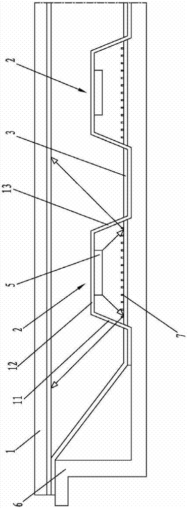
[0030] Such as figure 2 , image 3 As shown, the embodiment of the backlight module of the present invention includes a diffuser plate 1 and a light source device 2 and a first reflector 3 that are both arranged on the back side of the diffuser plate 1 . The light source device 2 is disposed between the diffuser plate 1 and the first reflection plate 3 for providing light to the diffuser plate 1 . The light emitting surface of the light source device 2 faces the first reflector 3 , and the first reflector 3 reflects the light emitted by the light source device 2 to the diffusion plate 1 . The back plate 6 is disposed on the back of the first reflection plate 3 for enhancing the overall strength of the backlight module. image 3 The hollow arrows in show the light propagation path.
[0031] In the embodiment of the backlight module of the present invention, the light emitted by the light source device in the direct type backlight module does not directly enter the diffusion...
Embodiment 2
[0042] combine Figure 5 As shown, the difference between the embodiment of the backlight module of the present invention and the first embodiment lies in the arrangement of the light source 5 in the light source device 2 .
[0043] In the embodiment of the backlight module of the present invention, the light source 5 is fixed on the inner surface of the first board 11 . The light emitted by the light source 5 is reflected by the second plate body 12 and the third plate body 13 to the first reflection plate 3 , and the first reflection plate 3 reflects the light to the diffuser plate 1 . Figure 5 The hollow arrows in show the light propagation path.
Embodiment 3
[0045] combine Image 6 As shown, the difference between the embodiment of the backlight module of the present invention and Embodiment 1 and Embodiment 2 lies in the arrangement of the light sources 5 in the light source device 2 .
[0046] In the embodiment of the backlight module of the present invention, the light source 5 is fixed on the surface of the second plate 12 facing the first reflector 3 and the inner surface of the first plate 11 . The light emitted by the light source 5 is either reflected by the second board 12 and the third board 13 to the first reflector 3 , or directly hits the first reflector 3 , and the first reflector 3 reflects the light to the diffuser 1 .
PUM
 Abstract
Description
Claims
Application Information
 - R&D
- Intellectual Property
- Life Sciences
- Materials
- Tech Scout
- Unparalleled Data Quality
- Higher Quality Content
- 60% Fewer Hallucinations
Browse by: Latest US Patents, China's latest patents, Technical Efficacy Thesaurus, Application Domain, Technology Topic, Popular Technical Reports.
© 2025 PatSnap. All rights reserved.Legal|Privacy policy|Modern Slavery Act Transparency Statement|Sitemap|About US| Contact US: help@patsnap.com


