
Cam control clutch power transmission distributor

A technology of transmission distributor and cam control, which is applied to transmission devices, belts/chains/gears, mechanical equipment, etc. It can solve the problems of inability to realize three-axis power transmission control, large structure occupation space, complex control, etc., and achieve compact structure , large carrying capacity and high transmission efficiency

Inactive Publication Date: 2013-03-20
ANHUI UNIVERSITY OF TECHNOLOGY
View PDF6 Cites 5 Cited by
  • Summary
  • Abstract
  • Description
  • Claims
  • Application Information

AI Technical Summary

Problems solved by technology

The existing clutch technology can only control the power transmission and interruption from one shaft to another shaft, and cannot realize the power transmission control between three shafts
Although the combination of two clutches and gear transmission can realize the power transmission and control between the three shafts, but two sets of control mechanisms are required, the structure takes up a lot of space, and the control is more complicated
Whether it is electromagnetic clutch control, or hydraulic or pneumatic clutch control, keeping the clutch disengaged or engaged for a long time consumes a lot of energy

Method used


Image

  • Cam control clutch power transmission distributor
  • Cam control clutch power transmission distributor
  • Cam control clutch power transmission distributor

Examples


Embodiment Construction

[0018] The present invention will be described in detail below in conjunction with the accompanying drawings and embodiments.

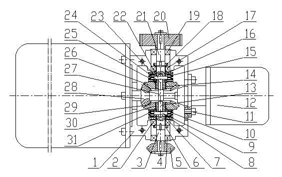
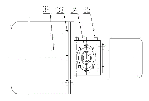
[0019] Lower casing 1 and upper casing 34 are fixed together to form casing with bolt 35, and the flange connection of main motor 32 on the left side of the casing is fixed with screw 33, and the flange connection of control motor 12 on the right side of the casing is fixed with screw 11. In the case, the driving gear 28 is fixed on the shaft end of the main motor 32 through a spline connection, and meshes with the front driven gear 29 and the rear driven gear 26 on both sides at the same time; The shaft end, the rear driven gear 26 is vacantly sleeved on the shaft end of the output shaft 21, and the two can rotate freely on the output shaft; The driven gear and the rear driven gear are positioned axially. Front bearing shell 30 and rear bearing shell 14 are respectively fixedly installed in the endoporus of front driven gear 29 and rear driven g...


PUM


Abstract

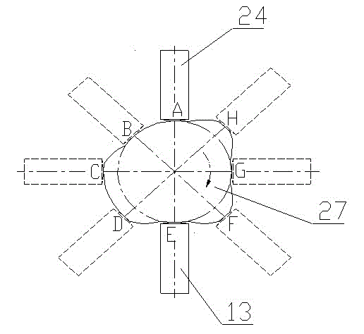
The invention provides a cam control clutch power transmission distributor, which belongs to the technical field of transmission machinery. The distributor consists of a base, a transmission gear system, clutches, output shafts and a cam-carrier rod mechanism, wherein the transmission gear system consists of a driving gear, a front driven gear and a back driven gear; two groups of clutches of completely the same structure are positioned on both sides of a cam axis; the axis of the driving gear is coaxial with or vertical to the cam axis; the two driven gears are hollowly sleeved at one ends of the output shafts respectively, and are meshed with end face teeth of the clutches; a cam is used for pushing a carrier rod to move in an output shaft hole for controlling the clutches to be switched on / off; and by changing the power transmission relations of the driving gear and the two output shafts, the function of switching among four power transmission states is realized. The cam control clutch power transmission distributor disclosed by the invention has the advantages of compact structure, high bearing capability, low energy consumption, high working reliability, and wide application to mechanical transmission systems.

Description

technical field [0001] The invention belongs to the technical field of transmission machinery, and in particular relates to a cam-controlled clutch power transmission distributor. Background technique [0002] In all kinds of automatic processing machine tools, automatic assembly and logistics transportation and other production machinery, power transmission distributors with single input and multiple outputs are required. Especially for small aerial transport trolleys, both the lifting and fast movement of goods require power transmission, but the transmission of the two is carried out alternately. In order to reduce the self-weight and occupied space of the trolley, it is the most ideal choice to use a single motor drive and a power transmission distributor to realize the alternate work of the lifting mechanism and the moving mechanism. The existing clutch technology can only control the power transmission and interruption from one shaft to another shaft, and cannot reali...

Claims


Application Information

Patent Timeline
IPC IPC(8): F16H37/12
Inventor 张玉华
Owner ANHUI UNIVERSITY OF TECHNOLOGY
Learn More