Chain lathedog and concrete pumping system

A clamp and chain technology, which is applied to variable capacity pump components, components of pumping devices for elastic fluids, pumps, etc., can solve the problems of loose clamp connection, time-consuming and laborious disassembly process, and piston falling off, etc. , to achieve the effect of durable and reliable clamping connection, convenient disassembly and installation, and reliable fastening effect

Inactive Publication Date: 2013-03-20
XUZHOU XCMG CONSTR MACHINERY CO LTD BUILDING MACHINERY
View PDF8 Cites 10 Cited by
  • Summary
  • Abstract
  • Description
  • Claims
  • Application Information

AI Technical Summary

Problems solved by technology

[0003] The flange structure between the main pumping cylinder 1 and the piston 2 is connected by a clamp 5. Therefore, the clamp is a very important connecting piece. As the piston reciprocates in the delivery cylinder, it is frequently subjected to Alternating load and vibration can easily lead to the loosening of the clamp connection and the fatigue fracture of the fastening bolt, which will cause the piston to fall off and seriously affect the pumping construction
[0004] On the other hand, since the piston is a vulnerable part, there is a problem of regular replacement of the piston, and the replacement of the piston is inside the water tank, and the space layout inside the water tank is very compact, so the clamp also needs to meet the requirements of easy disassembly, safety and reliability
[0005] Existing commonly used clamp structures such as Figure 2A , 2B , 3A, 3B, 4A, 4B, where Figure 2A , 2B The figure shows the clamp ring + four bolt connection form. This clamp has high reliability, but the alignment of the upper and lower clamp bolt holes is inconvenient and requires multiple adjustments, and the four screws need to be misaligned in diagonal order. Time-consuming and labor-intensive disassembly process
Figure 3A , 3B It shows the form of the cassette clamping the upper and lower semicircular clamps. This form is more convenient for disassembly and assembly, but the bolts for the cassette are limited by the structural space, so the size is small. Combined with manufacturing errors and field assembly conditions, the bolts are often used. There are over-tightening and bending moment problems, and it is very easy to break
Figure 4A , 4B What is shown is the form of direct axial fixation without clamps, which is inconvenient to disassemble and assemble, and the space arrangement is also relatively difficult
[0006] From the several common clamp structures introduced above, it can be seen that there is still a lack of durable, reliable and easy-to-assemble clamp structures for application in concrete pumping systems.

Method used


Image

  • Chain lathedog and concrete pumping system
  • Chain lathedog and concrete pumping system
  • Chain lathedog and concrete pumping system

Examples


Embodiment Construction

[0031] The technical solutions of the present invention will be described in further detail below with reference to the accompanying drawings and embodiments.

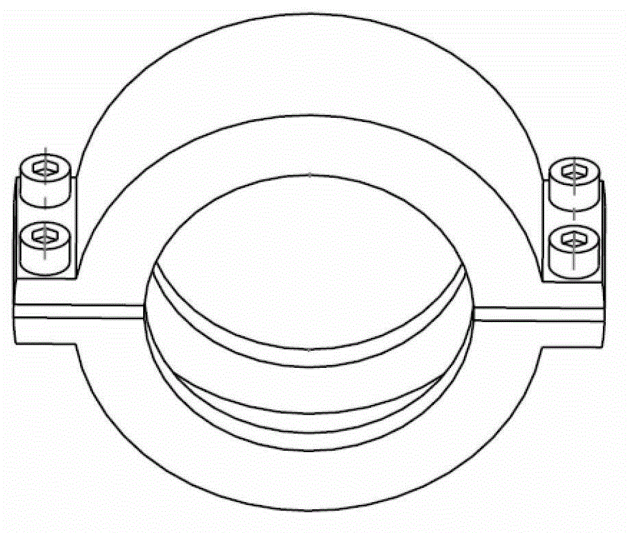
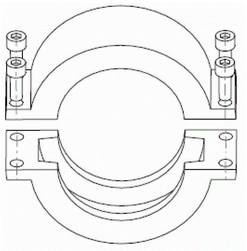
[0032] like Figure 5 As shown, it is a structural schematic diagram of an embodiment of the chain clamp of the present invention in an unfolded state. from Figure 5 It can be seen from the figure that the chain clamp in this embodiment includes a first clamp 1, a second clamp 2 and a connecting rod 3, wherein the first end of the first clamp 1 and the first end of the second clamp 2 The ends can be fixedly connected by bolts and nuts (see Image 6 ), the second end of the first clamp 1 and the second end of the second clamp 2 are respectively hinged with the two ends of the connecting rod 3, and the first clamp 1 and the second clamp 2 can rotate relative to the connecting rod 3 into the closed or expanded state.

[0033] from Image 6 It can be seen that one end of the first clamp 1 and the second clamp 2 of th...


PUM


Abstract

The invention relates to a chain lathedog and a concrete pumping system. The chain lathedog comprises a first lathedog, a second lathedog and connecting rods, wherein the first end of the first lathedog and the first end of the second lathedog are fixedly connected by bolts and nuts, the second ends of the first lathedog and the second lathedog are respectively articulated with both ends of the connecting rods, and the first lathedog and the second lathedog can rotate to a closed state or unfolded state, corresponding to the connecting rods. According to the chain lathedog disclosed by the invention, one ends of the two lathedogs are articulated with the connecting rods, and the first lathedog and the second lathedog can rotate to a certain angle corresponding to the connecting rods, so that the chain lathedog is conveniently unfolded and closed and is enabled to be jointed with the fitting surface of a flange to be clamped as much as possible; the connecting rods play the role of tightening reliably and assist the two lathedogs in positioning when the two lathedogs close, and convenience is brought in mounting the bolts and the nuts; and the bolts and the nuts only need to be mounted at one ends of the two lathedogs, so that the number of the needed bolts and nuts is less, and more convenience is brought in the disassembly and the assembly.

Description

technical field [0001] The invention relates to the field of engineering machinery, in particular to a chain clamp and a concrete pumping system. Background technique [0002] Concrete pumping system is a construction machinery system that transports concrete to a designated location. figure 1 A schematic diagram of the structure of an example of an existing concrete pumping system is given in , and its structure includes a piston 2, a main pumping cylinder 1, a delivery cylinder 3, a water tank 4, a clamp 5, etc. The actuator of the pumping system can use the hydraulic pressure to drive the piston 2 to reciprocate, so that the concrete can be transported to the pouring position against the resistance of the pipeline. The delivery cylinder 3 is a cylindrical part, the piston 2 moves inside to suck or pump out the concrete, the water tank 4 can cool, lubricate, clean the internal parts and check the tightness of the piston, and also serves as the main pumping cylinder 1 And...

Claims


Application Information

Patent Timeline
Patent Type & Authority Applications(China)
IPC IPC(8): F04B53/00F04B15/02
Inventor 沈千里李明玉杨宝东张卫国
Owner XUZHOU XCMG CONSTR MACHINERY CO LTD BUILDING MACHINERY
Why Eureka
Try Eureka