
Working pipe system of spinal paramedian keyhole approach

A technology of working pipes and keyholes, which is applied in the field of medical devices, can solve the problems of poor opening effect of the operation area, increased operation risk, and long surgical incision, so as to help postoperative recovery, shorten operation time, and reduce surgical trauma. small effect

Active Publication Date: 2013-03-20
陈春美 +6
View PDF3 Cites 1 Cited by
  • Summary
  • Abstract
  • Description
  • Claims
  • Application Information

AI Technical Summary

Problems solved by technology

[0002] During spinal surgery, in order to prevent the muscles, blood vessels, trachea, esophagus, thyroid and other tissues on both sides of the incision from affecting the surgical operation, it is necessary to glass and stretch the tissues on both sides of the spine at the incision. Currently, a forceps brace is commonly used. When using the spreader, the spreader needs to be placed in the incisions on the left and right sides or the upper and lower ends of the surgical site respectively, relying on the operation of the operation to separate the tissue to the two sides and expose the vertebral body for easy operation. Leaf strength is not high
The distal end of the blade tends to cohere, and the method of spreading is single. Since at least two spreaders are required to play a role, the surgical incision needs to be longer, which not only increases the pain of the patient, but also is difficult to heal after the operation, and the effect of spreading the surgical area is insufficient. Good, affects visual field, complex operation, increases surgical risk, does not conform to the concept of minimally invasive spinal surgery
In addition, the diameter of similar working channels at home and abroad is generally large in clinical use, and the paravertebral muscles, especially the multifidus muscles, etc. are damaged after use, and the price is expensive, which increases the operation cost of patients.

Method used


Image

  • Working pipe system of spinal paramedian keyhole approach
  • Working pipe system of spinal paramedian keyhole approach
  • Working pipe system of spinal paramedian keyhole approach

Examples


Embodiment Construction

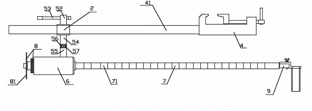
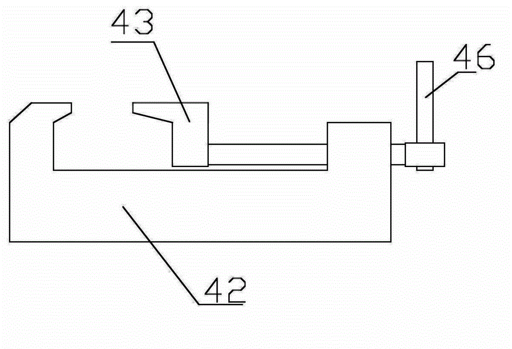
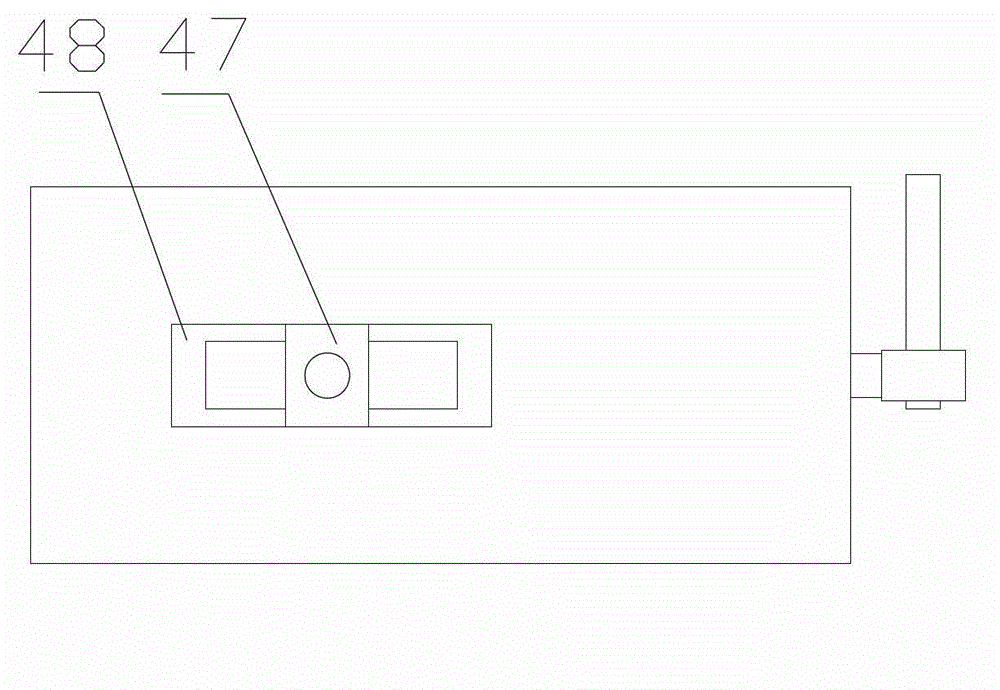
[0023] Such as figure 1 , 11 As shown in ~15: it includes a fixing device, an operation channel tube 1 with a fixing slot, a puncture positioning needle 2, a set of expansion tubes 3 whose diameters increase sequentially, and the operation channel tube is fixed on the fixing device through the fixing slot 11, The specification of the expansion tube is that the diameter of the inner wall of the expansion tube of the upper level is equal to the diameter of the outer wall of the expansion tube of the next level, and the outer diameter of the largest expansion tube is equal to the inner diameter of the operation channel tube. During the operation, the thread is positioned by the puncture positioning needle and punctured to the operation area, and then the expansion tube is guided by the positioning needle to be inserted. The method of inserting the expansion tube is to first select the expansion tube with the smallest diameter, and move inward along the direction of the puncture p...


PUM

PropertyMeasurementUnit
The inside diameter ofaaaaaaaaaa

Abstract

The invention relates to a working pipe system of a spinal paramedian keyhole approach, which is convenient to operate, good in stability and good for view after location at the operation area. The working pipe system comprises a fixing device, an operation channel pipe with a fixed clamping groove, a puncture locating needle and a set of dilation tubes with gradually increased diameters, wherein the operation channel pipe is fixed on the fixing device through the fixed clamping groove; and the specification of each dilation tube is that the internal side wall diameter of the upper level of dilation tube is equal to the external side wall diameter of the next level of dilation tube, and the external diameter of the dilation tube at the largest level is equal to the internal diameter of the operation channel pipe. The working pipe system can greatly shorten the operation time by that after location of the puncture locating needle, the dilation tubes are continuously inserted into the operation area, and at last the operation channel tube is inserted into and aligned with the operation area, and compared with the traditional operation, the time is shortened by 1 hour. The invention has the advantages that the working pipe system is simple to operate; the operation wound is small; the damage to bones and muscles during the operation is reduced; and the working pipe system facilitates postoperative rehabilitation and reduces complication and the like.

Description

technical field [0001] The invention relates to the field of medical instruments, in particular to a paraspinal median keyhole approach working pipeline system. Background technique [0002] During spinal surgery, in order to prevent the muscles, blood vessels, trachea, esophagus, thyroid and other tissues on both sides of the incision from affecting the surgical operation, it is necessary to glass and stretch the tissues on both sides of the spine at the incision. Currently, a forceps brace is commonly used. When using the spreader, the spreader needs to be placed in the incisions on the left and right sides or the upper and lower ends of the surgical site respectively, relying on the operation of the operation to separate the tissue to the two sides and expose the vertebral body for easy operation. Leaf strength is not high. The distal end of the blade tends to cohere, and the method of spreading is single. Since at least two spreaders are required to play a role, the sur...

Claims


Application Information

Patent Timeline
IPC IPC(8): A61B17/00
Inventor 陈春美陈权王春华韦浩王锐石松生杨卫忠
Owner 陈春美
Learn More