
Multifunctional current-type bidirectional AC (Alternating-Current)/DC (Direct-Current) converter and control method thereof

A control method and converter technology, applied in reactive power adjustment/elimination/compensation, AC power input conversion to DC power output, electrical components, etc., can solve system reliability reduction, commutation control complexity, high cost, etc. question

Active Publication Date: 2014-08-27
CENT SOUTH UNIV
View PDF4 Cites 1 Cited by
  • Summary
  • Abstract
  • Description
  • Claims
  • Application Information

AI Technical Summary

Problems solved by technology

Although this structure realizes the bidirectional flow of energy, it has the following problems: 1) There are many power devices, the commutation control is complicated, and the reliability of the system is reduced; 2) When charging, only the step-down rectification can be realized. 3) The system is directly affected by the voltage fluctuation of the power grid, and the stability is reduced; 4) The clamp protection circuit is complex, takes up a large volume, and has a high cost
At the same time, when there are a large number of equipment with frequent changes in reactive power in the users of the power system, their active and reactive powers change rapidly with time, resulting in fluctuations or flickering of supply voltage, waveform distortion, deterioration of power factor and unbalanced load. Causes dynamic unbalance of three-phase voltage, thereby deteriorating the power quality of the power grid, which requires the charging device to have the ability to improve the quality of the power grid in some occasions

Method used


Image

  • Multifunctional current-type bidirectional AC (Alternating-Current)/DC (Direct-Current) converter and control method thereof
  • Multifunctional current-type bidirectional AC (Alternating-Current)/DC (Direct-Current) converter and control method thereof
  • Multifunctional current-type bidirectional AC (Alternating-Current)/DC (Direct-Current) converter and control method thereof

Examples


Embodiment 1

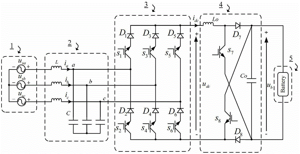
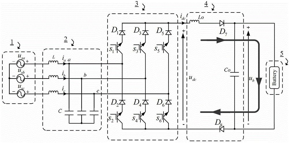
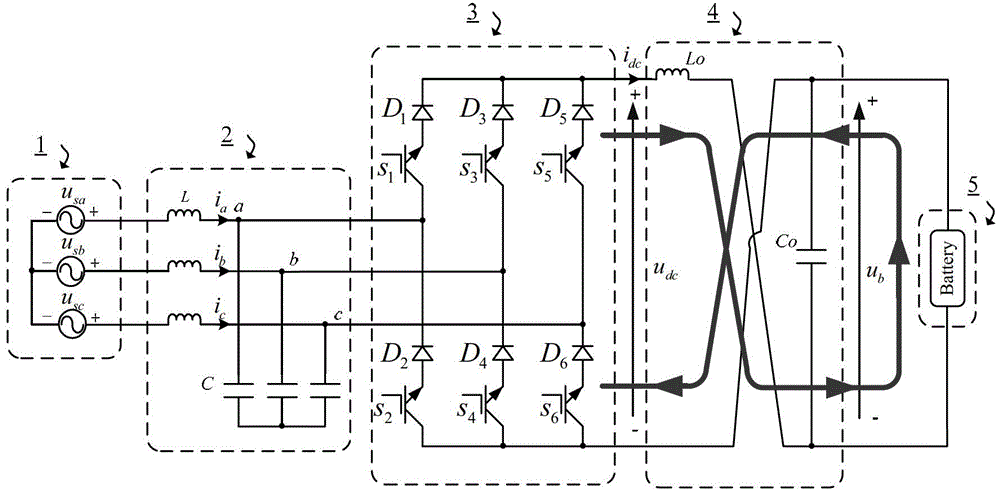
[0069] Such as Figure 7 As shown, the multifunctional current-mode bidirectional AC / DC converter topology and controller include an input filter, a three-phase current-mode rectifier, a DC side filter inductor, an auxiliary switch network, a data acquisition unit and a DSP control unit. The input filter is a second-order low-pass LC filter, which is composed of a filter capacitor C and a filter inductor L. It is mainly used to filter out high-frequency harmonics caused by the switching action of the converter, where L=1.0mH, C=15μF .. The three-phase current-mode PWM rectifier includes 6 IGBT power switch tubes S 1 , S 2 , S 3 , S 4 , S 5 , S 6 and 6 power diodes D 1 、D 2 、D 3 、D 4 、D 5 and D 6 . Its DC output side is connected to the auxiliary switch network through the DC inductor Lo. The auxiliary switch network consists of two IGBT(s 7 and s 8 ) and two power diodes (D 7 and D 8 ): switch s 7 collector and diode D 7 The anodes are connected together an...


PUM


Abstract

The invention discloses a multifunctional current-type bidirectional AC (Alternating-Current) / DC (Direct-Current) converter and a control method thereof. The multifunctional current-type bidirectional AC-DC converter comprises an input filter, a three-phase current type rectifier, a direct-current lateral filtering inductor and an auxiliary switch network; and the AC / DC converter works according to any one of five modes. The AC / DC converter is compact in structure and realizes an energy bidirectional flow function through a smaller quantity of switches; and meanwhile, the system cost can be reduced. If a voltage at a chargeable battery end is lower than a maximum output voltage of the current type AC / DC converter, so that the single-stage charging can be realized and the system efficiency is high. If the voltage at the chargeable battery end is higher than the maximum output voltage of the current type AC / DC converter, the AC / DC converter works in a boosting mode by properly controlling an auxiliary network, and the charging requirements can be satisfied. Therefore, the AC / DC converter has wider voltage applicable range. According to the requirement of a power grid, the topology further can be used for reactively compensating and the like.

Description

technical field [0001] The invention relates to a multifunctional current-type bidirectional AC / DC converter and a control method thereof, belonging to the technical field of power electronics. Background technique [0002] With the depletion of global oil resources and the increasingly prominent environmental problems, electric vehicles or hybrid electric vehicles have become one of the current research hotspots. Electric vehicle on-board battery charging and discharging technology is the key technology for the development of electric vehicles, but traditionally the grid only charges electric vehicles, and for electric vehicles parked for a long time, not only the energy stored in the battery has not been well utilized, but also To some extent, it will affect the battery life. With the introduction and development of the smart grid concept, people are exploring and researching a new model: when the vehicle power battery needs to be charged, the electric energy flows from t...

Claims


Application Information

Patent Timeline
Patent Type & Authority Patents(China)
IPC IPC(8): H02M7/797H02J3/18
CPCY02E40/30
Inventor 孙尧粟梅王辉李幸杨建刘尧张关关刘永露韩华熊文静
Owner CENT SOUTH UNIV
Learn More