
Liquid crystal optics

A technology of liquid crystal optics and devices, which is applied in optics, nonlinear optics, instruments, etc., can solve the problems of slowing the reaction speed of the liquid crystal layer, and achieve the effects of reducing disorder, reducing optical characteristics, and suppressing electric field leakage

Inactive Publication Date: 2016-09-14
JAPAN DISPLAY INC
View PDF5 Cites 0 Cited by
  • Summary
  • Abstract
  • Description
  • Claims
  • Application Information

AI Technical Summary

Problems solved by technology

Therefore, the reaction speed of the liquid crystal layer decreases

Method used


Image

  • Liquid crystal optics
  • Liquid crystal optics
  • Liquid crystal optics

Examples


no. 3 approach

[0033] 4. The third embodiment (etc.)

[0034] [Explanation about the entire liquid crystal optical device according to the embodiment of the present invention]

[0035] In the liquid crystal optical device according to the embodiment of the present invention, the voltage value applied to the shielding electrode can be appropriately selected according to the design. From the viewpoint of reducing the types of voltages to be applied, it is preferable that the same voltage of a fixed value is applied to the common electrode and the shield electrode.

[0036] A spacer may be formed on a surface of the first substrate facing the liquid crystal layer or on a surface of the second substrate facing the liquid crystal layer. It is preferable that the spacer is formed on the second substrate facing the liquid crystal layer from the viewpoint of easy formation of the strip electrodes. In this structure, the shield electrode can be formed as an electrode integrated with the common elec...


PUM

PropertyMeasurementUnit
widthaaaaaaaaaa

Abstract

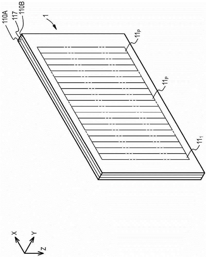
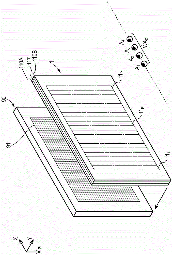
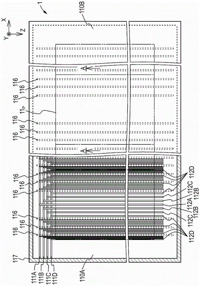
The invention discloses a liquid crystal optical device, comprising: a first substrate with a plurality of transparent strip electrodes formed in groups in each given area; a second substrate with a transparent common electrode; and a liquid crystal layer covered by Arranged between the first substrate and the second substrate, wherein, according to the voltage applied between the common electrode and the strip electrode, the retardation distribution is controlled in each given area, wherein, between the first substrate and the second substrate The portion corresponding to the boundary of a given area between has wall spacers, and a shielding electrode for applying a voltage of a fixed value is provided on at least one of the two wall surfaces of each spacer.

Description

technical field [0001] The invention relates to a liquid crystal optical device. Background technique [0002] As an optical device capable of changing the refractive index of a lens, such as that of JP-A-2001-133928 (Patent Document 1) figure 2 As shown in , for example, a liquid crystal optical device having a structure in which a liquid crystal layer is arranged between a pair of transparent substrates having transparent electrodes is proposed. In the liquid crystal optical device having this structure, the refractive index of the lens can be changed by controlling the retardation distribution in the liquid crystal layer by changing the voltage between the pair of substrates. [0003] In a liquid crystal optical device in which lenses are formed by smoothly changing the retardation distribution in a liquid crystal layer, since optical lenses are formed, the thickness of the liquid crystal layer must be set significantly thicker than that in a general liquid crystal displ...

Claims


Application Information

Patent Timeline
Patent Type & Authority Patents(China)
IPC IPC(8): G02F1/1343G02B30/28
CPCG02F1/133377G02F1/13394G02F1/134309G02F2201/128G02F1/29G02B30/28G02F1/1343G02F1/1335G02F1/1339G02B30/27
Inventor 高间大辅小糸健夫大山毅
Owner JAPAN DISPLAY INC
Learn More