
Electric strength inspection device for oil paper compound insulation oil during flowing

A technology of composite insulation and electric strength, applied in the direction of testing dielectric strength, material breakdown voltage, etc., can solve the problems of processing error, installation difficulty, flashover, etc., and achieve the effect of improving flashover voltage and preventing flashover.

Inactive Publication Date: 2013-03-13
STATE GRID CORP OF CHINA +1
View PDF5 Cites 17 Cited by
  • Summary
  • Abstract
  • Description
  • Claims
  • Application Information

AI Technical Summary

Problems solved by technology

[0004] The purpose of the present invention is to solve the problem that the existing electric strength inspection device is difficult to install due to processing errors, and flashovers often occur, and provides an electric strength inspection device for oil-paper composite insulating oil flow

Method used


Image

  • Electric strength inspection device for oil paper compound insulation oil during flowing

Examples


specific Embodiment approach 1

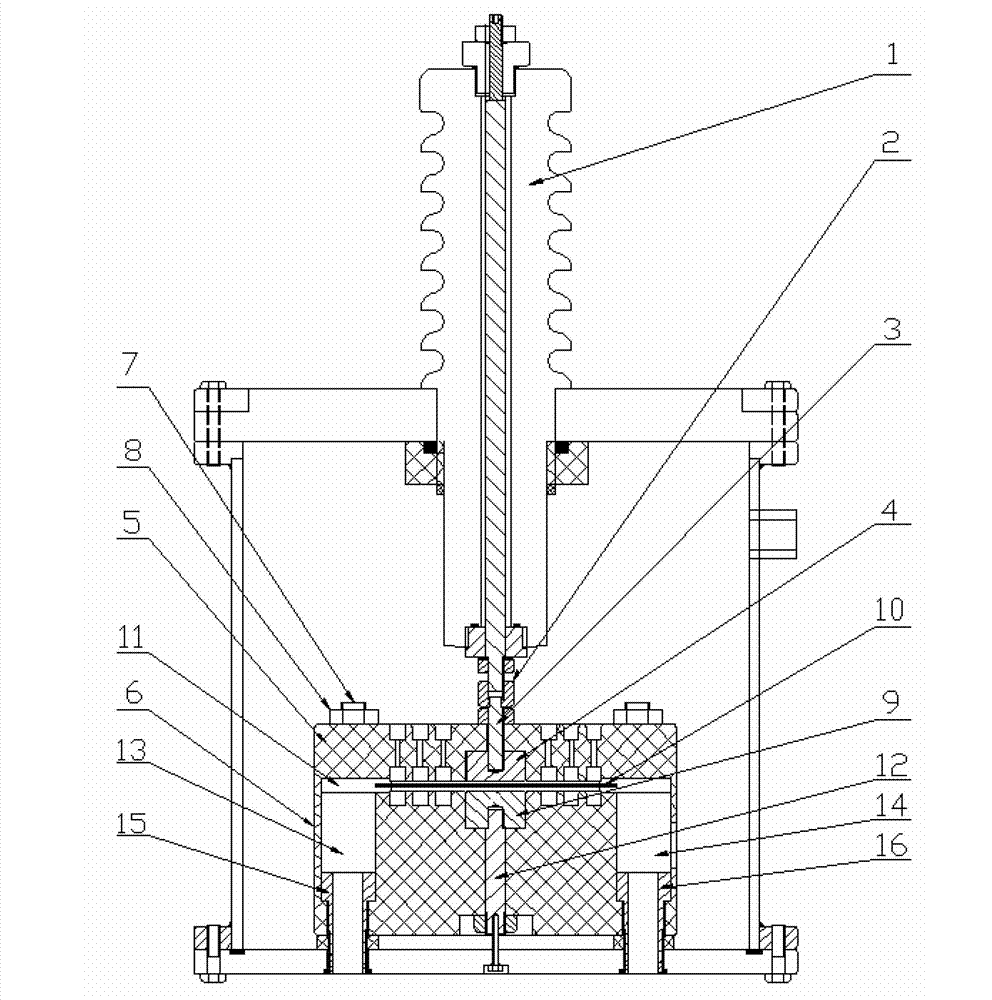
[0014] Specific implementation mode one: the following combination figure 1 Describe this embodiment, the oil-paper composite insulating oil flowing down electric strength testing device described in this embodiment, it includes high voltage bushing 1, high voltage bushing lower connector 2, upper electrode connector 3, upper electrode 4, upper electrode insulator 5. Lower electrode insulation 6, insulating screw 7, insulating nut 8, lower electrode 9, insulating cardboard 10, oil channel 11, grounding bolt 12, oil inlet 13, oil outlet 14, oil inlet connector 15 and Oil outlet connector 16,

[0015] High-voltage bushing lower connector 2, upper electrode connector 3, upper electrode 4, upper electrode insulator 5, lower electrode insulator 6, insulating screw 7, insulating nut 8, lower electrode 9, insulating cardboard 10, oil passage 11 and the ground bolt 12 are set in the high-pressure test box,

[0016] The upper electrode 4 is arranged directly above the lower electrode...

specific Embodiment approach 2

[0022] Embodiment 2: In this embodiment, Embodiment 1 is further described. The connection between the upper electrode connector 3 and the lower connector 2 of the high-voltage bushing is connected by a dynamic fit. Prevent connection difficulties due to the accumulation of machining errors, thereby introducing high potential into the upper electrode.

specific Embodiment approach 3

[0023] Embodiment 3: This embodiment further describes Embodiment 1. The inner surfaces of the upper electrode insulator 5 and the lower electrode insulator 6 are milled with multiple grooves. To increase the flashover voltage and prevent flashover from happening.


PUM


Abstract

The invention relates to an electric strength inspection device for oil paper compound insulation oil during flowing, belongs to the technical field of high voltage and insulation, and aims at solving the problems of difficulty in mounting and frequent flashover caused by processing errors of the existing electric strength inspection devices. The electric strength inspection device comprises a high-voltage bushing, a lower connecting piece of the high-voltage bushing, an upper electrode connecting piece, an upper electrode, an upper electrode insulating member, a lower electrode insulating member, an insulating screw rod, an insulating nut, a lower electrode, an insulating paper board, an oil duct, an earthing bolt, an oil inlet, an oil outlet, an oil inlet connecting piece and an oil outlet connecting piece, wherein the low connecting piece of the high-voltage bushing, the upper electrode connecting piece, the upper electrode, the upper electrode insulating member, the lower electrode insulating member, the insulating screw rod, the insulating nut, the lower electrode, the insulating paper board, the oil duct and the earthing bolt are arranged in a high-voltage test box, the upper electrode is arranged right above the lower electrode and is embedded in the upper electrode insulating member, the lower electrode is embedded in the lower electrode insulating member, and the upper electrode insulating member is arranged above the lower electrode insulating member.

Description

technical field [0001] The invention relates to a device for testing the electric strength of oil-paper composite insulating oil flowing down, and belongs to the technical field of high voltage and insulation. Background technique [0002] With the continuous growth of the national economy and the increasing demand for energy, high-voltage long-distance power transmission has become a strategic issue affecting economic development. The National Energy Leading Group Office listed UHV power grid construction as a key point of energy work. The improvement of transformer voltage level makes the requirements for transformer insulation higher and higher. At present, oil-paper insulation is still used as the main form of internal insulation of transformers due to manufacturing process and insulation performance. With the increase of transformer capacity, the requirements for transformer heat dissipation performance are also greatly improved. One of the effective measures to improv...

Claims


Application Information

Patent Timeline
Patent Type & Authority Applications(China)
IPC IPC(8): G01N27/92G01R31/12
Inventor 陈庆国池明赫高源魏新劳王永红
Owner STATE GRID CORP OF CHINA
Learn More