Thrust valve

A thrust and valve shell technology, which is applied in the field of pipeline switch valves, can solve the problems of inflexible rotation of ball valves, and achieve the effects of light weight, wide application and smooth medium flow.

Inactive Publication Date: 2014-07-23
邓连友 +1
View PDF6 Cites 0 Cited by
  • Summary
  • Abstract
  • Description
  • Claims
  • Application Information

AI Technical Summary

Problems solved by technology

[0002] At present, there are many kinds of pipeline valves and are widely used, but they not only control the flow of gas and liquid in the pipeline, but also control the flow of gas and liquid carrying dust and dirt. Valves for Dirty Media Flow Come to Market Early
With the continuous development of science and technology, the pipeline has become the artery for transporting gas and liquid all over the world. The key to controlling the movement of the flowing medium in the pipeline is to set up valves. There are many types of existing valves, mainly including ball valves, plate valves and butterfly valves. Each has distinct characteristics, but each has its fatal disadvantages. The ball valve is not flexible to rotate, the plate valve needs to be rotated dozens of times to switch in place, and the butterfly valve is only suitable for controlling the flow of low-temperature medium.

Method used


Image

  • Thrust valve
  • Thrust valve
  • Thrust valve

Examples


Embodiment 1

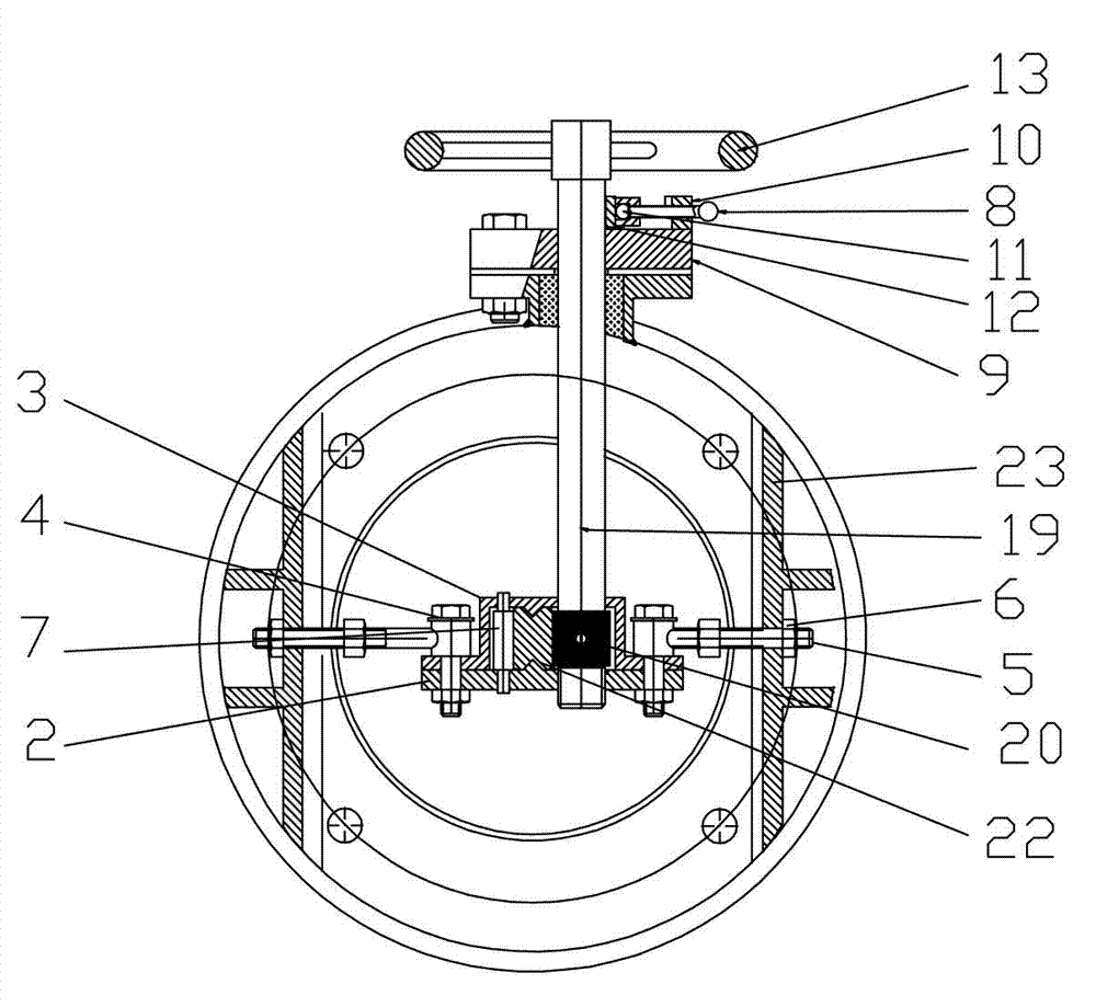
[0025] Such as figure 1 , figure 2 The thrust valve shown has a main body structure of a cylindrical valve housing 1, a brake shaft 19 is designed perpendicular to the length surface of the valve housing, the brake shaft 19 passes through the valve housing 1, and the top of the brake shaft 19 is equipped with The handwheel 13, the outer periphery of the brake shaft connected to the valve casing is designed with a sealing seat 9, and the sealing material is filled in the sealing seat 9; a positioning nut 10 is designed on the sealing seat 9, and a handle 8 is worn in the positioning nut, and the end of the handle 8 is The limit ball 11, the brake pad 12 is installed between the limit ball 11 and the brake shaft 19, the positioning nut, the handle, the limit ball, and the brake pad constitute the braking system; the inner wall of the valve housing 1 is fixed with a support positioning plate 23 ; The supporting positioning plate 23 is connected with a positioning rod 5, and the...

Embodiment 2

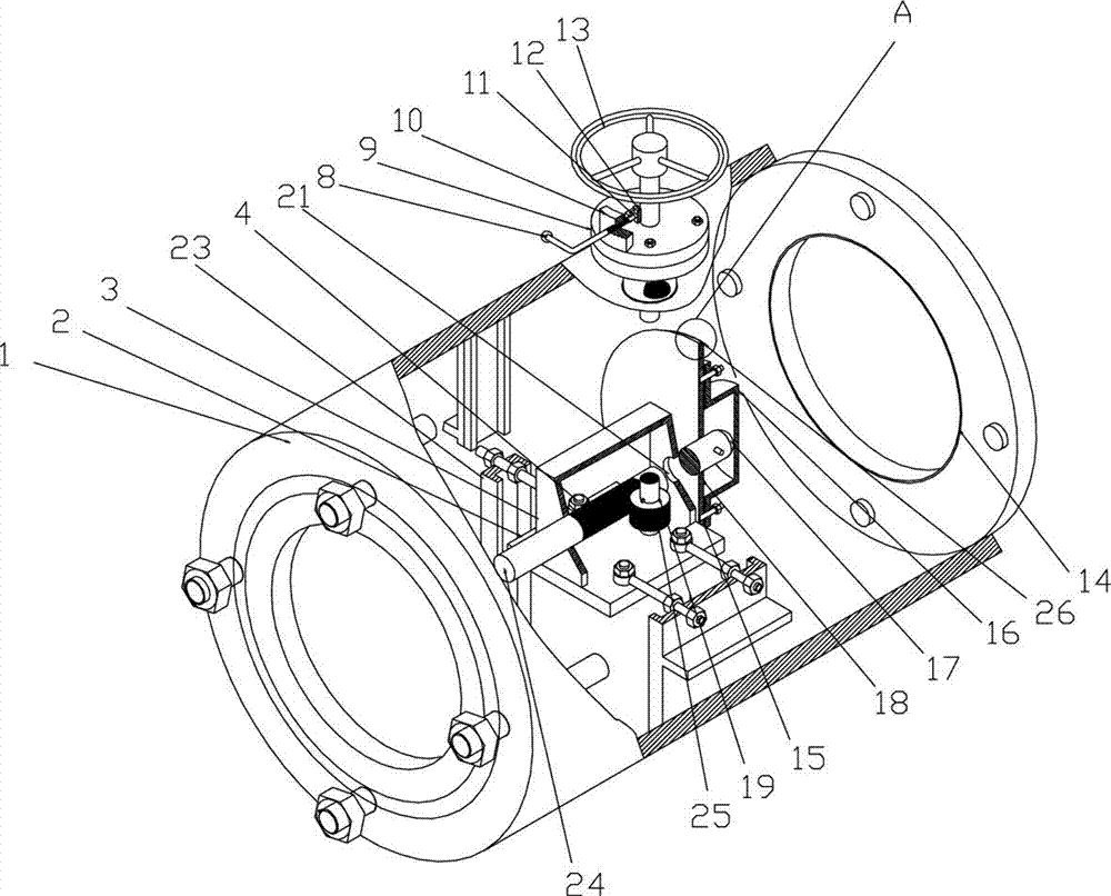
[0028] Such as image 3 , Figure 4 The thrust valve shown has a main body structure of a cylindrical valve housing 1, a brake shaft 19 is designed perpendicular to the length surface of the valve housing, the brake shaft 19 passes through the valve housing 1, and the top of the brake shaft 19 is equipped with The handwheel 13, the outer periphery of the brake shaft connected to the valve casing is designed with a sealing seat 9, and the sealing material is filled in the sealing seat 9; a positioning nut 10 is designed on the sealing seat 9, and a handle 8 is worn in the positioning nut, and the end of the handle 8 is The limit ball 11, the brake pad 12 is installed between the limit ball 11 and the brake shaft 19, the positioning nut, the handle, the limit ball, and the brake pad constitute the braking system; the inner wall of the valve housing 1 is fixed with a support positioning plate 23 ; The support positioning plate 23 is connected with a positioning rod 5, and the po...


PUM


Abstract

The invention discloses a thrust valve. The main body structure of the thrust valve is a cylindrical valve shell, wherein a braking shaft is designed in a manner vertical to the length surface of the valve shell; a supporting and positioning plate is fixed on the inner wall of the valve shell; a positioning rod is connected to the supporting and positioning plate; a steering transmission mechanism is fixed in the valve shell through the other end of the positioning rod; the braking shaft is an input shaft of the steering transmission mechanism; an outer edge conical valve plate which is vertical to an output shaft of the steering transmission mechanism is connected to the output shaft; the outer edge of the outer edge conical valve plate is an inclined surface; an inner edge wide-mouth flange is arranged at one end of the valve shell; the closing of a valve body is realized under the cooperation of the inner edge wide-mouth flange and the outer edge conical valve plate; and conical decontamination teeth are designed on the outer edge circumference of the outer side vertical wall of the outer edge conical valve plate. The thrust valve has the advantages that: after the thrust valve is opened or closed, a good sealing effect is achieved, and a decontamination function is realized simultaneously. The thrust valve has wide application, and is particularly suitable for braking large and middle-sized sewage-carrying gas-liquid pipelines.

Description

technical field [0001] The invention relates to a pipeline switch valve, in particular to a valve for controlling the flow of gas and liquid carrying dust and dirt in pipelines. Background technique [0002] At present, there are many kinds of pipeline valves and are widely used, but they not only control the flow of gas and liquid in the pipeline, but also control the flow of gas and liquid carrying dust and dirt. Valves for the flow of dirty media entered the market early. With the continuous development of science and technology, the pipeline has become the artery for transporting gas and liquid all over the world. The key to controlling the movement of the flowing medium in the pipeline is to set up valves. There are many types of existing valves, mainly including ball valves, plate valves and butterfly valves. , Each has distinct characteristics, but all have their fatal disadvantages. The ball valve is not flexible to rotate, the plate valve needs to be rotated dozens...

Claims


Application Information

Patent Timeline
Patent Type & Authority Patents(China)
IPC IPC(8): F16K1/00F16K1/38F16K31/53
Inventor 张务谨邓连友刘声凯邓森
Owner 邓连友
Why Eureka
Try Eureka