
Positioning assembly device

A technology for assembling devices and sleeves, used in hand-held tools, manufacturing tools, etc., can solve problems such as poor sealing of the shaft and housing, scratches on the sealing ring on the shaft, affecting the normal operation of the machine, etc. The effect of prolonging the service life

Active Publication Date: 2013-03-06
ZHEJIANG PIONEER MACHINERY & ELECTRON
View PDF8 Cites 7 Cited by
  • Summary
  • Abstract
  • Description
  • Claims
  • Application Information

AI Technical Summary

Problems solved by technology

In the prior art, the sealing ring on the shaft is usually pressed into the mounting hole between the shaft and the housing, so that the inner hole of the sealing ring on the shaft fits with the shaft, and the outer circle fits with the mounting hole of the housing to achieve sealing. However, when the sealing ring on the shaft is pressed into the shaft, because the sealing ring on the shaft is not positioned, the pressure on various parts of the ring edge of the sealing ring on the shaft will be uneven during the process of pressing in, resulting in the sealing ring on the shaft The deflection will make the outer circle of the sealing ring on the shaft and the housing not concentric, which will cause the sealing ring on the shaft to be easily scratched by the opening of the mounting hole of the housing, resulting in poor sealing between the shaft and the housing, affecting the normal operation of the machine run

Method used


Image

  • Positioning assembly device
  • Positioning assembly device
  • Positioning assembly device

Examples


Embodiment Construction

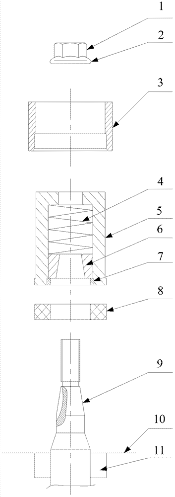
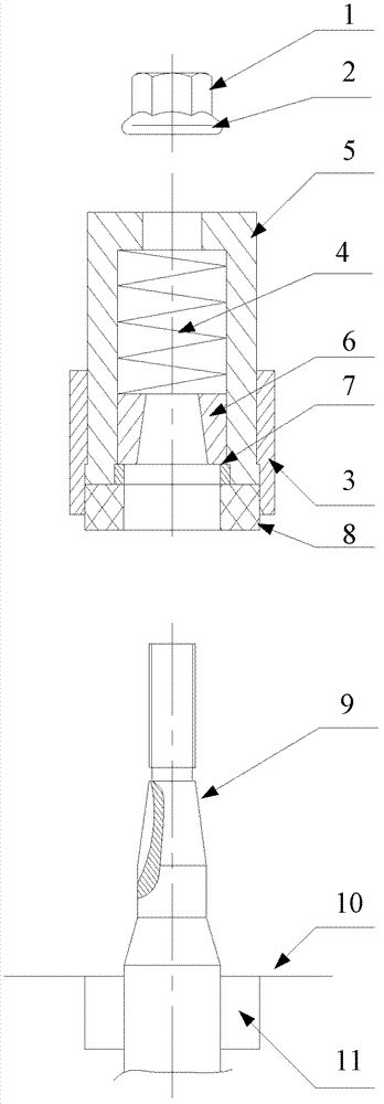
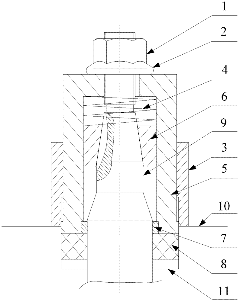
[0027] The invention provides a positioning and assembling device, which is used for installing the sealing ring on the shaft, avoids scratching of the sealing ring on the shaft caused by the shell due to improper installation, thereby improving its sealing performance and prolonging its service life.

[0028] The technical solutions in the embodiments of the present invention will be clearly and completely described below in conjunction with the accompanying drawings in the embodiments of the present invention. Obviously, the described embodiments are only some, not all, embodiments of the present invention. Based on the embodiments of the present invention, all other embodiments obtained by persons of ordinary skill in the art without making creative efforts are all

[0029] Belong to the protection scope of the present invention.

[0030] Such as figure 1 As shown, the positioning assembly device provided in this embodiment includes:

[0031] The top end of the sleeve 5 i...


PUM


Abstract

The invention discloses a positioning assembly device which is used for mounting of an on-shaft seal ring (8) of a countershaft (9). The positioning assembly device comprises a sleeve (5), a taper ring (6), a spring (4), a retainer ring (7) and a positioning ferrule (3). The top end of the sleeve (5) is provided with a hole with the diameter smaller than that of a cavity of the sleeve (5); the outer wall of the taper ring (6) is closely attached to the inner wall of the sleeve (5), taper ring (6) is capable of moving axially along the sleeve (5), and the center of the taper ring (6) is provided with a taper hole with the diameter smaller than that of the bottom end; the spring (4) is arranged in the sleeve (5) and positioned between the taper ring (6) and the top end of the sleeve (5); the retainer ring (7) is arranged in the sleeve (5) and positioned in a cylindrical opening at the bottom end of the taper ring (6); and the positioning ferrule (3) is sleeved on the sleeve (5), and the inner wall of the positioning ferrule (3) is attached to the outer side wall of the on-shaft seal ring (8). Using the positioning assembly device for mounting the on-shaft seal ring, scratch damage between the on-shaft seal ring and a shell can be prevented, and weakening of tightness caused by scratch of the on-shaft seal ring by the shell due to improper mounting can be avoided.

Description

technical field [0001] The invention relates to the technical field of mechanical assembly, more specifically, to a positioning assembly device. Background technique [0002] With the rapid development of the machinery industry on a global scale, the development of the machinery manufacturing industry and the self-sufficiency level of machinery and equipment have become the real symbols to measure a country's economic development level and scientific and technological level. The mechanical seal structure is a structure often used in the machinery manufacturing industry, especially the structure of the seal ring on the shaft is more common. [0003] The shaft seal ring plays a key role in the hydraulic or pneumatic system, but it has very high requirements for the installation environment. Once the installation environment is affected, it is very easy to be damaged. At the same time, the shaft seal is easily damaged due to improper placement. It can be seen , The sealing rin...

Claims


Application Information

Patent Timeline
IPC IPC(8): B25B27/02
Inventor 杨慧明徐旭彪
Owner ZHEJIANG PIONEER MACHINERY & ELECTRON
Learn More