Pelvic support structure for physical therapy device and head fastener for cervical traction

A physical therapy, pelvic technology, applied in physical therapy, application, surgical instrument support, etc., can solve problems such as inability to accurately fix the head, side effects, inconvenience, etc., to prevent the dispersion of force, comfort and firm support, convenience fixed effect

Inactive Publication Date: 2013-02-27
郑元夏
View PDF4 Cites 15 Cited by
  • Summary
  • Abstract
  • Description
  • Claims
  • Application Information

AI Technical Summary

Problems solved by technology

[0008] The present invention is invented in order to solve the existing problems as described above, and its purpose is to provide a pelvic support structure for a physical therapy instrument and a head fixation device for pulling the cervical spine. It can support the pelvis more comfortably and firmly, and can maintain a predetermined traction strength without being untied or slipped, thereby preventing the dispersion of force during physical therapy for the lumbar spine, and concentrating the traction on the lumbar spine can improve the therapeutic effect. When used as a medical instrument or device for traction of the cervical spine (neck), it can solve the problem of inconvenience when used for corrective or therapeutic purposes, and the problem of side effects during use due to the inability to fix the head accurately

Method used


Image

  • Pelvic support structure for physical therapy device and head fastener for cervical traction
  • Pelvic support structure for physical therapy device and head fastener for cervical traction
  • Pelvic support structure for physical therapy device and head fastener for cervical traction

Examples


Embodiment Construction

[0026] Hereinafter, the technical configuration of the present invention will be described in detail with reference to the drawings.

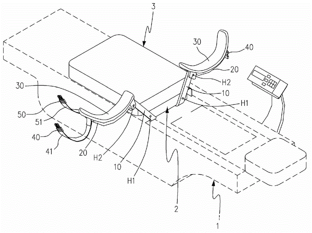
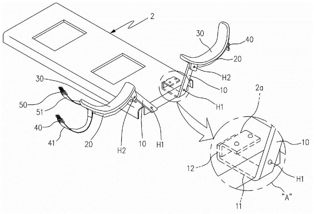
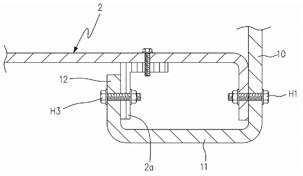
[0027] The pelvic support structure for physical therapy apparatus of the present invention, such as Figure 1 to Figure 6a As shown in . and 6b, the physical therapy apparatus is composed of a bottom plate 2 that can be moved back and forth on the upper part of the frame 1 and a pelvic bed 3 that is close to the upper part of the bottom plate 2 for supporting the lumbar spine, including: a bracket 10, respectively with a shaft H1 rotatably connected to both sides of the front of the bottom plate 2; the pelvic support member 20, which is bent and formed to surround the pelvis, and is connected to the upper part of the bracket 10 rotatably left and right with the axis H2; the pelvic buffer pad 30, Respectively arranged on the inner surface of the pelvic support 20 and closely attached to the pelvis; the inner and outer buckles 40, 50 are respecti...


PUM


Abstract

The present invention concerns a pelvic support structure for a physical therapy device and a head fastener for cervical traction, which supports a pelvis in a comfortable and firm manner, maintains a predetermined level of traction intensity without being detached or slid down, maximizes a treatment effect by concentrating a traction force on the lumbar and preventing power dispersion, is intended for patient treatment or correction by means of cervical traction, and does not pressurize a patient's head or function in an unstable manner. For a physical therapy device comprising a bed plate (2) disposed at an upper portion of a frame (1) such that the bed plate (2) may move backwards and forwards and a pelvic bed (3) attached to an upper portion of the bed plate (2) to support the lumbar, the pelvic support structure of the present invention comprises: brackets (10) connected by means of shafts (H1) to both front sides of the bed plate (2) in a rotatable manner; pelvic supporters (20) connected by means of shafts (H2) to upper portions of the brackets (10) in a rotatable manner and having a curved shape to surround a pelvis; pelvic cushions (30) disposed at inner surfaces of the pelvic supporters (20) to come into tight contact with the pelvis; and female and male buckles (40 and 50) connected to upper portions of the pelvic supporters (20) and the pelvic cushions (30) by means of bands (41 and 51), the female and male buckles (40 and 50) being one-touch detachable type.

Description

technical field [0001] The present invention relates to a pelvic support structure for a physical therapy instrument and a head fixation device for pulling the cervical spine. Open or slide to maintain a predetermined traction strength, thereby preventing the dispersion of the force, concentrating the traction on the lumbar spine can improve the therapeutic effect, and use it for the purpose of correcting or treating patients by tractioning the cervical spine, so as not to compress the patient's head Pelvic support structure for physiotherapy apparatus and head immobilization device for cervical traction. Background technique [0002] In general, physical therapy devices use drop and traction to treat and correct pain that occurs in the skeleton system, joint system, muscle system, and nervous system of the human body, and various types of medical physical therapy devices are provided. [0003] The physical therapy apparatus needs to support the lumbar spine comfortably and...

Claims


Application Information

Patent Timeline
Patent Type & Authority Applications(China)
IPC IPC(8): A61F5/045A61H1/00A61F5/01
CPCA61H1/0222A61H2201/1607A61H1/0218A61H2205/081A61H2203/0456A61H2201/163A61B19/26A61B90/50
Inventor 郑元夏
Owner 郑元夏
Why Eureka
Try Eureka