
Sunlight indoor lighting fiber transmission device and operation method thereof

An indoor lighting and conduction device technology is applied in the field of solar energy utilization to achieve the effect of improving position resolution and compact appearance

Inactive Publication Date: 2013-02-27
NORTH CHINA ELECTRIC POWER UNIV (BAODING)
View PDF4 Cites 15 Cited by
  • Summary
  • Abstract
  • Description
  • Claims
  • Application Information

AI Technical Summary

Problems solved by technology

[0005] The purpose of this patent invention is to address the defects of existing solar fiber optic lighting devices and tracking methods, solve the problems mentioned in the background technology while realizing building integration, improve the reliability and tracking accuracy of photosensitive positioning devices, and meet the requirements of actual building installations. In order to solve the problem of application, a kind of solar indoor lighting optical fiber transmission device and its working method are proposed

Method used


Image

  • Sunlight indoor lighting fiber transmission device and operation method thereof
  • Sunlight indoor lighting fiber transmission device and operation method thereof
  • Sunlight indoor lighting fiber transmission device and operation method thereof

Examples


Embodiment Construction

[0040] The present invention will be further described below in conjunction with the accompanying drawings and embodiments.

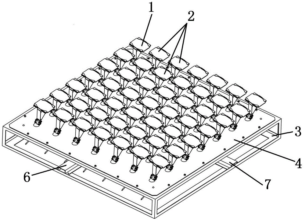
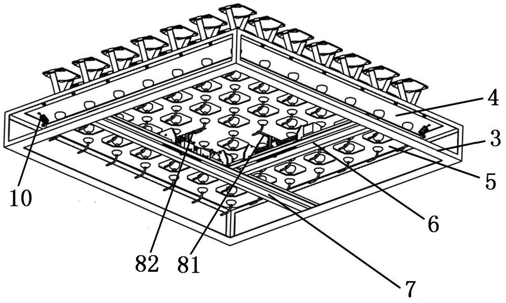
[0041] figure 1 and figure 2 They are the upper and lower structural schematic diagrams of the embodiment of the solar indoor lighting optical fiber transmission device, respectively. The solar indoor lighting optical fiber transmission device is composed of a positioning unit, a lighting unit, a plate frame, a fixed plate, a movable plate and a driving mechanism.

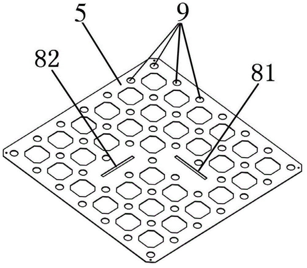
[0042] The plate frame 3 is a rectangular or square double-layer frame. The shape and size of the fixed plate 4 are the same as the upper frame of the plate frame 3. The fixed plate 4 is fixed on the upper frame of the plate frame 3. The circular double ball joint positioning hole 9 Arrange evenly on the fixed plate 4 according to 5-25 rows and 5-25 columns. Such as image 3 As shown, the number and arrangement of the double ball joint positioning holes 9 on the movable plate 5 are the s...


PUM


Abstract

The invention relates to a sunlight indoor lighting fiber transmission device and an operation method thereof, which belongs to the technical field of solar energy. The sunlight indoor lighting fiber transmission device comprises a positioning unit, lighting units, a plate frame, a fixed plate, a movable plate and a driving mechanism, wherein double ball joints of the lighting units and the positioning unit are arranged in double ball joint positioning holes and are clamped by the fixed plate and the movable plate to form a parallel double ball joint combined mechanical mechanism; the movable plate is driven by the driving mechanism so that the lighting units and the positioning unit swing parallely when the lighting units and the positioning unit track the sun; and cross arrangement of positioning fibers on a cross positioning fiber connector and optical coupling formed by the positioning fibers corresponding to light sensitive elements are used for realizing synchronous tracking of the sun by all the lighting units of the sunlight indoor lighting fiber transmission device. The sunlight indoor lighting fiber transmission device has the advantages that the sunlight indoor lighting fiber transmission device has compact appearance and is of a plate structure, installation positions are not limited to roofs, the sunlight indoor lighting fiber transmission device can be suspended on external walls of buildings, building integration is promoted, and the sunlight indoor lighting fiber transmission device is suitable for natural lighting in shady rooms and basements.

Description

technical field [0001] The invention belongs to the technical field of solar energy utilization, and in particular relates to a solar indoor lighting optical fiber conduction device and a working method thereof. Background technique [0002] Optical fiber transmission lighting technology is to effectively collect sunlight and use optical fiber to transmit it to places that need lighting. This lighting technology is energy-saving, photoelectrically isolated, very safe, and its spectrum is also suitable for human health needs. The core idea of ​​this type of technology is to use a condenser lens or a condenser mirror to focus the sunlight onto the optical fiber, and use the optical fiber to transmit the sunlight to the place that needs to be illuminated. However, in practical applications, it is necessary to consider the issue of building integration and sun tracking accuracy. It must not only have a compact appearance, but also need a reliable, accurate, and cheap tracking sy...

Claims


Application Information

Patent Timeline
IPC IPC(8): F21S11/00F21V13/02G05D3/00
Inventor 宋记锋靳周杨勇平
Owner NORTH CHINA ELECTRIC POWER UNIV (BAODING)
Learn More