
Hybrid lift type impeller

A lift-type blade and lift-type technology, which is applied to wind turbines, hydroelectric power generation, wind turbines and other directions that are consistent with the wind direction, can solve problems such as weak working ability, insufficient working ability, and no directional adaptability. Good start-up and control of power speed

Inactive Publication Date: 2014-12-10
HOHAI UNIV
View PDF6 Cites 0 Cited by
  • Summary
  • Abstract
  • Description
  • Claims
  • Application Information

AI Technical Summary

Problems solved by technology

Moreover, although the traditional lift type vertical shaft turbine does not have the problem of direction adaptability
However, the feature of its blades absorbing work twice makes it have the problem that the first work ability is insufficient, the second work ability is extremely weak, and the overall work ability is weak.

Method used

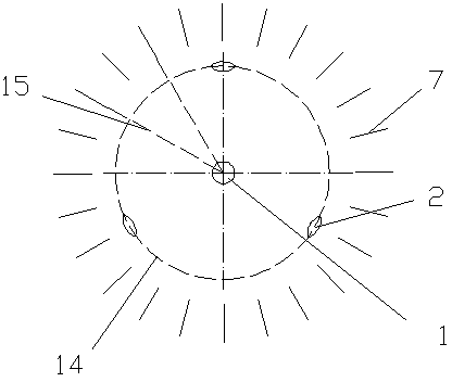
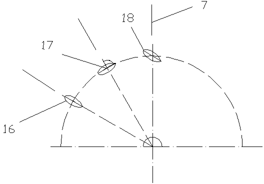

Image

  • Hybrid lift type impeller
  • Hybrid lift type impeller
  • Hybrid lift type impeller

Examples


Embodiment Construction

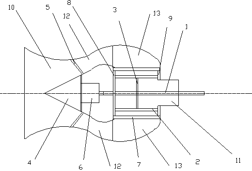
[0024] The present invention will be described in detail below in conjunction with the accompanying drawings. Such as figure 1 As shown, the hybrid impeller of the present invention, the main body of the impeller includes a rotating shaft 1, on which two or more equal-section lift-type blades 2 are installed; one end of the blade is connected to a circular end cover 8 , the other end of the blade is connected with the annular end cover 9. The generator 6 driven by the impeller is fixed inside the closed conical flow guide 4, and the conical flow guide 4 is fixed inside the inlet flow channel 10 through the bracket 5, and the conical flow guide 4 is also located in the impeller upstream. A grille 7 is arranged around the impeller, and a water outlet channel 11 is arranged downstream of the impeller.

[0025] The fluid first enters the inlet channel 10, and under the influence of the conical shroud 4, the fluid enters the inlet channel 10 from the fluid inlet, passes through ...


PUM


Abstract

The invention discloses a hybrid lift type impeller. The hybrid lift type impeller comprises a rotating shaft, two or more than two lift type vanes, an electric generator and a casing, the lift type vanes are arranged on the rotating shaft, the electric generator is connected with the rotating shaft, the casing is provided with a fluid inlet and a fluid outlet, a tapered flow guide cover is disposed in the middle in the casing, the electric generator is mounted in the tapered flow guide cover, the lift type vanes are located in the fluid outlet, an annular channel is formed between the tapered flow guide cover and the casing, a flow gathering chamber is formed between the lift type vanes and the casing, the annular channel is communicated with the flow gathering chamber, grids are annularly distributed at an outlet of the flow gathering chamber, and the grids are parallel to the lift type vanes. By means of the hybrid lift type impeller, water flow changes from transverse flowing to longitudinal flowing under the combined action of an inlet flow channel, the flow guide cover, the annular flow channel, the flow gathering chamber and the grids sequentially, the water flow flows into a vane working area along the normal direction of the vane rotating circle, so that the lift type vanes can obtain an optimal fluid dynamic field, and the working capacity of the vanes is improved.

Description

technical field [0001] The invention relates to a novel wind power machine and a sea current energy water turbine. Background technique [0002] At present, most water turbines use high water head pressure to do work, and this type of water turbine has higher efficiency when the water head is high. However, for rivers with low water head or even some slight water heads, if traditional hydraulic turbines that rely on pressure to do work are used to convert energy, the efficiency is low and the economy is poor. [0003] In the utilization of ocean current energy, there are also horizontal-axis turbines and vertical-axis lift-type turbines. These turbines have their own advantages and disadvantages. For horizontal-axis turbines, horizontal-axis turbines use lift-type blades, which have faster speeds and higher energy utilization. Relatively mature, and thus widely used. Although the efficiency of the horizontal axis wind turbine is high, its main working area is concentrated ...

Claims


Application Information

Patent Timeline
Patent Type & Authority Patents(China)
IPC IPC(8): F03B13/00F03B3/06F03B3/18F03D9/00F03D1/00F03D1/04
CPCY02E10/223Y02E10/72Y02E10/20
Inventor 赵振宙叶芬黄娟原红红郑源赵振宁
Owner HOHAI UNIV
Learn More