
Anti-rolling decoupling mechanism of magnetic levitation vehicle walking unit

An anti-roll decoupling mechanism and magnetic levitation technology, which is applied to railway car body parts, track contact elements, bogies, etc., can solve the problem of increasing the gap between modules and track design, reducing suspension and traction efficiency, and reducing anti-roll capacity, etc. problems, to achieve the effect of improving the ability to pass through curves, improve the decoupling ability, and increase the speed of curves

Inactive Publication Date: 2014-12-31
NAT UNIV OF DEFENSE TECH
View PDF6 Cites 0 Cited by
  • Summary
  • Abstract
  • Description
  • Claims
  • Application Information

AI Technical Summary

Problems solved by technology

[0007] In summary, the existing anti-roll decoupling mechanism of the running unit has the following deficiencies: 1. The existing anti-roll decoupling mechanism is installed at the front and rear ends of the module, resulting in a small decoupling rate; due to the height of the running unit Limitation, its decoupling ability is limited, which in turn limits the use of the running unit for smaller curve radius and highest curve speed
2. The anti-roll ability and decoupling ability of the existing anti-roll decoupling mechanism are interrelated and restrict each other. The improvement of decoupling ability will lead to the decrease of anti-roll ability, and vice versa
This leads to a certain compromise in the design. In order to meet the decoupling capability, a certain anti-roll capability must be sacrificed to allow the module to have a certain roll angle, thereby increasing the design gap between the module and the track, and reducing the suspension and traction efficiency. Increased energy consumption

Method used


Image

  • Anti-rolling decoupling mechanism of magnetic levitation vehicle walking unit
  • Anti-rolling decoupling mechanism of magnetic levitation vehicle walking unit
  • Anti-rolling decoupling mechanism of magnetic levitation vehicle walking unit

Examples


Embodiment Construction

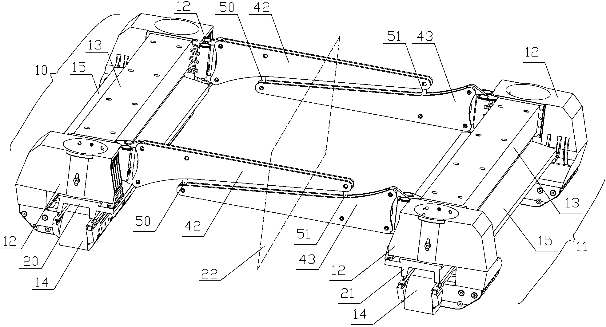
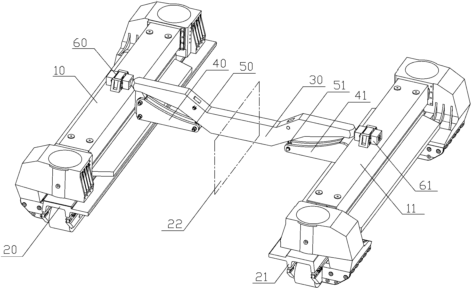
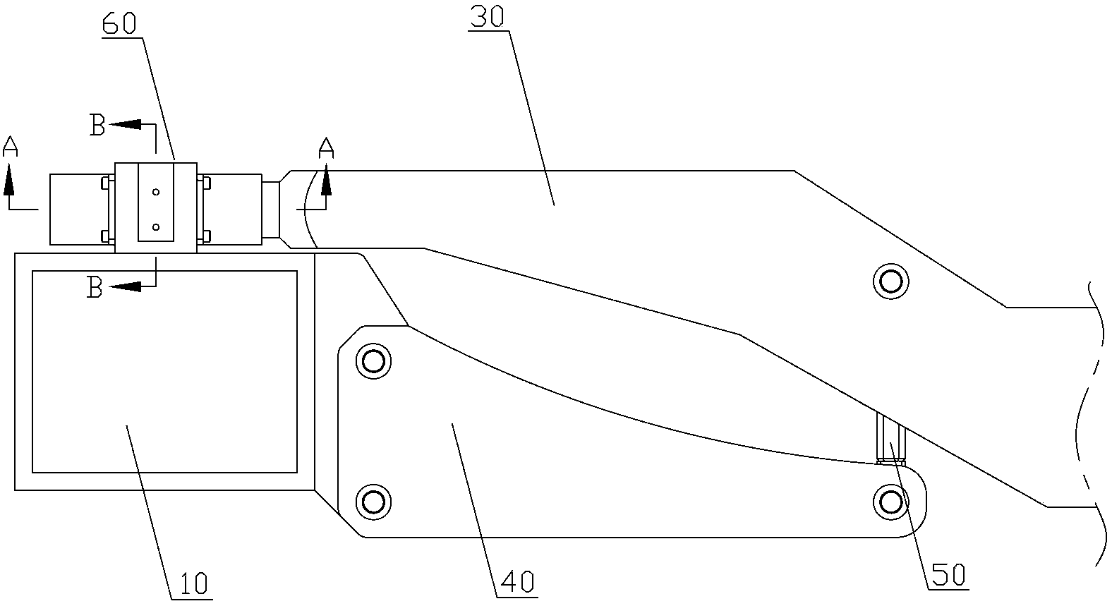
[0026] figure 2It is a schematic diagram of the installation of the present invention on the running unit of the suspended vehicle. The anti-roll decoupling mechanism of the running unit of the magnetic levitation vehicle provided by the present invention is composed of a center beam 30, two anti-roll beams, two suspenders and two sets of spherical hinge linear combined bearings, which are arranged on the running unit along the vertical track direction On the middle section of the track, it is integrated with two suspension modules arranged left and right along the direction of the track, forming an "H"-shaped layout. One end of the left anti-roll beam 40 in the two anti-roll beams is fixedly connected to the left suspension module 10 at the middle section position, and the other end is connected to the lower end of the left suspender 50 through a ball joint; one end of the right anti-roll beam 41 is connected to the right suspension module 11 in the The middle section posit...


PUM


Abstract

The invention discloses an anti-rolling decoupling mechanism of a magnetic levitation vehicle walking unit, which aims to reduce the mutual influences of anti-rolling and decoupling, improve an anti-rolling capability and a decoupling capability of the walking unit and improve a bent channel passing capability of the magnetic levitation vehicle walking unit. The technical scheme is that the anti-rolling decoupling mechanism is formed by a middle beam, two pieces of anti-rolling beams, two hanging rods and two sets of spherical hinge linearly combined bearings or spherical hinge bearings, which are distributed on a middle section of the walking unit along a direction which is vertical to a rail to be integrally connected with two suspension modules to form an H-shaped arrangement. The middle beam is in a left-right spherical hinge symmetrical structure; and the anti-rolling beams, the hanging rods and left and right structures of the spherical hinge linear combined bearings are the same and are symmetrically distributed relative to the central face of the rail. According to the anti-rolling decoupling mechanism of the magnetic levitation vehicle walking unit, the mutual restriction between the anti-rolling and the decoupling can be reduced; and the walking unit is applicable to a higher bent channel car speed and the bent channel passing capability of a magnetic levitation vehicle is improved.

Description

technical field [0001] The invention relates to an anti-roll decoupling mechanism for a running unit of a magnetic levitation vehicle. Background technique [0002] The line track of the maglev train is a spatial curved surface composed of two F rails with a certain cross-section and a certain relative positional relationship, and the center line of the line track is a spatial curve. The flat section of the maglev track (that is, the curve) usually consists of two transitional curves and a section of circular arc in the middle. The transitional curve is to realize the transition between the straight line and the circular arc. On the arc curve, the outer rail of the maglev track is usually designed to have a certain superelevation relative to the inner rail, that is, there is a certain cross-slope angle between the track section line and the horizontal plane. The slope angle is determined according to the design speed of the curve. The higher the speed of the curve, the smal...

Claims


Application Information

Patent Timeline
Patent Type & Authority Patents(China)
IPC IPC(8): B61F5/00B61F11/00
Inventor 刘耀宗邓文熙黎利华龚朴李杰张锟
Owner NAT UNIV OF DEFENSE TECH
Learn More