
A 10kv distribution network line strung optical cable spanning device

An optical cable and line technology, which is applied in the field of 10KV distribution network wiring and optical cable spanning devices, can solve the problems of damage to the outer insulation of the wire and wire, damage, structural damage, etc. damage effect

Active Publication Date: 2016-02-03
STATE GRID ZHEJIANG ELECTRIC POWER COMPANY DONGYANG POWER SUPPLY
View PDF3 Cites 0 Cited by
  • Summary
  • Abstract
  • Description
  • Claims
  • Application Information

AI Technical Summary

Problems solved by technology

The disadvantages of setting up the spanning frame and rope sliding: the spanning frame takes a long time to set up, there are many processes, and it is time-consuming and laborious
In the process of erecting 10KV conductors, most of the crossovers are low-voltage line communication and other optical cables, and the practical significance of erecting spanning frames is not obvious; the disadvantage of direct sliding of ropes: after sliding, it will cause damage to the structure of communication optical cables and other crossing lines. Damaged, the outer insulation and wire material of the wire will also be damaged after the wire passes through
Unable to meet the current requirements of safe and civilized production

Method used


Image

  • A 10kv distribution network line strung optical cable spanning device
  • A 10kv distribution network line strung optical cable spanning device
  • A 10kv distribution network line strung optical cable spanning device

Examples


Embodiment Construction

[0014] The present invention will be further described below in conjunction with the accompanying drawings and embodiments. While the invention will be described in conjunction with the preferred embodiments, it will be understood that it is not intended to limit the invention to the described embodiments. On the contrary, the invention is to cover alternatives, modifications and equivalents, which may be included within the scope of the invention as defined by the appended claims.

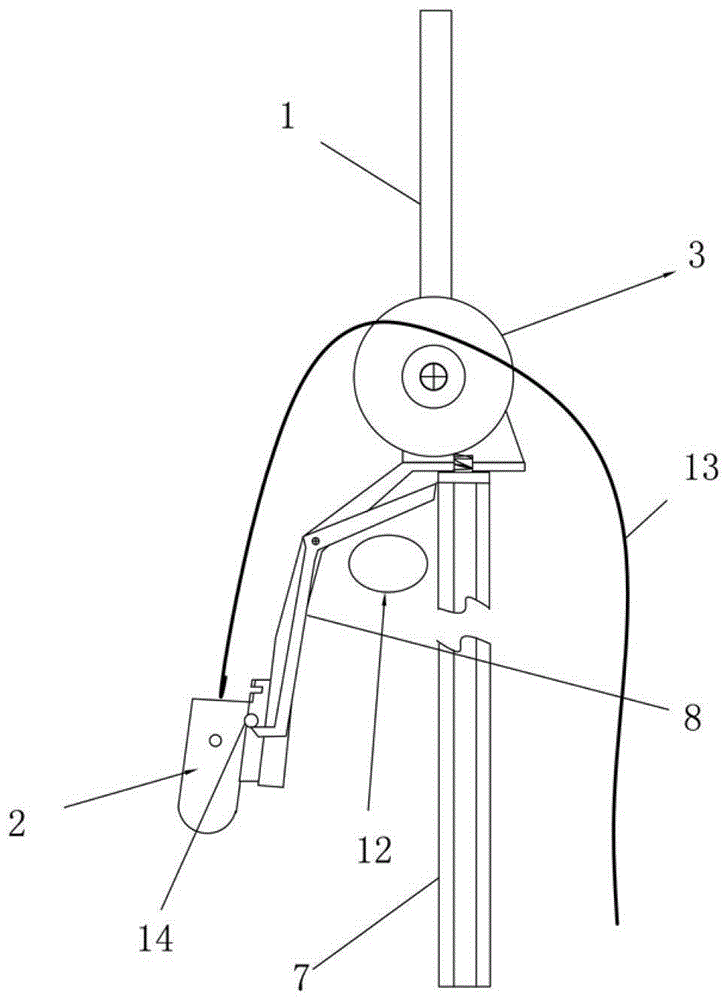
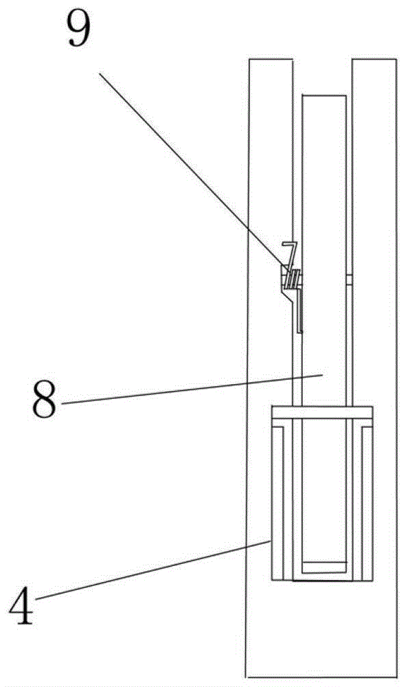
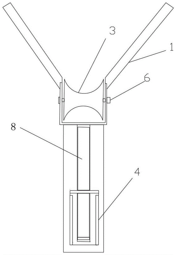
[0015] see Figure 1 to Figure 7 As shown, the 10KV distribution network line stringing optical cable spanning device includes a guide column 1, a gravity rope pendant 2, a spanning pulley 3, an operating rod 7, a heavy hammer trip lever 8, and a trip spring 9. The guide column 1 is located at On the spanning pulley 3 , the spanning pulley 3 is connected with a weight tripping rod 8 , and the end of the weight tripping rod 8 is provided with a fixed hook for hooking the gravity rope pendant 2 . ...


PUM


Abstract

The invention discloses a device enabling an erected line of a 10 KV distribution network to cross an optical cable. The device comprises a guiding column, a gravity rope weight, a crossing pulley, a handling rod, a counter weight releasing rod and a releasing spring. The guiding column is arranged on the crossing pulley, the crossing pulley is connected with the counter weight releasing rod, and a fixing hook for hooking up the gravity rope weight is arranged at the tail end of the counter weight releasing rod. The device has the advantages that the guiding column on the crossing device prevents a lead from not jumping out of the crossing device in a dragging process and is favorable for the device from rising. The handling rod is of a multi-joint assembling structure and is favorable for carrying and installing. The tail-end rod is locked through telescopic row-holes, height adjusting is flexible, and the handling rod is firm and reliable. The device can be installed on various optical cables of communication, broadcasting, electricity and low-voltage lines so as to be favorable for crossing of an erected lead fast and is convenient to carry and install. When the lead crosses the optical cable, the optical cable and the erected lead can be prevented from being damaged effectively.

Description

technical field [0001] The invention relates to an optical cable spanning device, more specifically, it relates to a 10KV distribution network line erecting optical cable spanning device. Background technique [0002] At present, crossing construction operations such as optical cables in the erection of 10KV distribution network lines mostly use spanning frames or directly use ropes to slide. The disadvantages of setting up the spanning frame and rope sliding ferry: the spanning frame takes a long time to set up, and there are many procedures, which are time-consuming and labor-intensive. In the process of erecting 10KV conductors, most of the crossovers are low-voltage line communication and other optical cables, and the practical significance of erecting spanning frames is not obvious; the disadvantage of direct sliding of ropes: after sliding, it will cause damage to the structure of communication optical cables and other crossing lines. After the wire passes through, it...

Claims


Application Information

Patent Timeline
Patent Type & Authority Patents(China)
IPC IPC(8): H02G1/04
Inventor 王新强吴国亮
Owner STATE GRID ZHEJIANG ELECTRIC POWER COMPANY DONGYANG POWER SUPPLY
Learn More