
Boot control circuit

A power-on control and switching circuit technology, applied in the field of electronics, can solve problems such as poor battery contact and power failure, save operation steps and boot time, and prevent damage

Active Publication Date: 2016-10-05
SHANGHAI MORUAN COMM TECH
View PDF4 Cites 0 Cited by
  • Summary
  • Abstract
  • Description
  • Claims
  • Application Information

AI Technical Summary

Problems solved by technology

[0003] However, such a power-on control circuit requires the user to operate the power-on button after installing the battery, especially when the mobile terminal is bumped, dropped, twisted or jolted, resulting in poor battery contact and power failure. , the mobile terminal is turned off, even after the battery is restored, the mobile terminal will not automatically turn on, but the user needs to manually press the power button to start

Method used


Image

  • Boot control circuit
  • Boot control circuit
  • Boot control circuit

Examples


Embodiment 1

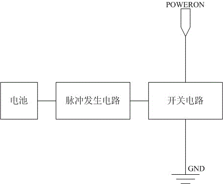
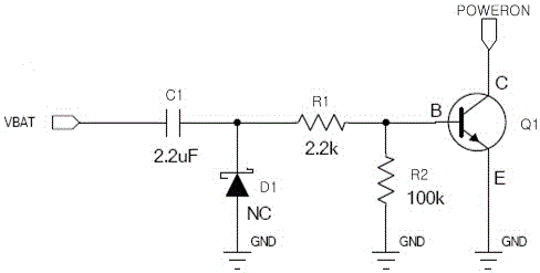
[0021] Such as figure 1 As shown, the present embodiment provides a power-on control circuit, including a low-level triggered power-on signal port (PowerOn), which is characterized in that: it also includes a pulse generating circuit for outputting a pulse signal when the remaining batteries are connected; and when A switch circuit that remains on when receiving the pulse signal, two ports of the switch circuit are respectively connected to the power-on signal port and the pulse generating circuit, and the other port of the switch circuit is grounded. Those skilled in the art can understand that when the pulse generating circuit is electrically connected to the power supply, the pulse signal is generated, and the switch circuit is kept in a conducting state under the control of the pulse circuit, and the power-on signal port is realized. Grounding means that the power-on signal port is at a low level, thereby triggering the mobile terminal to enter the power-on process. In th...

Embodiment 2

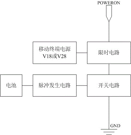
[0028] Such as image 3 As shown, this embodiment provides a power-on control circuit for preventing instantaneous power failure, including a low-level trigger power-on signal port (PowerOn), which is characterized in that: it also includes a pulse signal port for outputting a pulse signal when it is connected to a battery A pulse generating circuit; a switch circuit that remains on when receiving the pulse signal; and a time-limiting circuit with an on-time; two ports of the switch circuit are connected to one end of the time-limiting circuit and the pulse generating circuit respectively. The circuits are connected, and the other port of the switch circuit is grounded; the other two ends of the time-limiting circuit are respectively connected to the power-on signal port and the power supply of the mobile terminal. Those skilled in the art can understand that when the time-limiting circuit is kept in the conduction state during its conduction time, if the switch circuit is con...


PUM


Abstract

The invention discloses a starting-up control circuit. The starting-up control circuit comprises a starting-up signal port which is triggered by a low level, a pulse generation circuit which is used for output a pulse signal when other batteries are connected and a switching circuit which maintains a conducting state when receiving the pulse signal. Two ports of the switching circuit are connected with the starting-up signal port and the pulse generation circuit respectively, and another port of the switching circuit is grounded. According to the starting-up control circuit, automatic starting-up can be achieved only under the condition that the batteries are in good contact, convenience in operation for users can be provided, operation steps and the starting-up time are saved, a starting-up button can be prevented from being pressed frequently, and damage of the button is avoided.

Description

technical field [0001] The invention relates to the field of electronic technology, in particular to a power-on control circuit of a mobile terminal. Background technique [0002] The mobile terminal power-on control circuits of the prior art are all provided with a power-on signal port (PowerOn) and a power-on button switch, and the power-on signal port (PowerOn) is connected with the baseband chip. At this time, the level on the power-on signal port (PowerOn) is pulled low, so that the baseband chip can detect the low level on the power-on signal port (PowerOn), thereby controlling the mobile terminal to enter the power-on process. [0003] However, such a power-on control circuit requires the user to operate the power-on button after installing the battery, especially when the mobile terminal is bumped, dropped, twisted or jolted, resulting in poor battery contact and power failure. , the mobile terminal is thus turned off, even after the battery is restored to the conne...

Claims


Application Information

Patent Timeline
Patent Type & Authority Patents(China)
IPC IPC(8): H03K17/687
Inventor 刘继宅
Owner SHANGHAI MORUAN COMM TECH
Learn More