Backlight circuit, and method and terminal for controlling voltage of backlight circuit

A backlight circuit and voltage technology, applied in the field of terminal equipment, can solve the problems of low backlight efficiency, inability to guarantee backlight brightness, and voltage consumption.

Inactive Publication Date: 2013-02-13
ZTE CORP
View PDF5 Cites 11 Cited by
  • Summary
  • Abstract
  • Description
  • Claims
  • Application Information

AI Technical Summary

Problems solved by technology

The disadvantages of this circuit: if the anode provides a constant voltage, the efficiency of the backlight is very low at low brightness levels, and a considerable part of the power consumption is on the current control circuit module; if the battery voltage is used to provide voltage for the anode of the backlight, in addition to the above disadvantages One shortcoming is that the battery voltage gradually decreases with the prolongation of the working time of the terminal equipment. When the battery voltage drops to a certain level, the brightness of the backlight cannot be guaranteed. What's worse, when the power of the whole machine fluctuates, the brightness of the backlight fluctuates accordingly.
The screen brightness of terminal products often provides several levels for users to set. Although the backlight circuit with DC / DC function can make the screen work at the maximum brightness or the minimum brightness, it will not flicker due to the fluctuation of the whole machine power due to the decrease of the battery voltage. , but in fact, it is not necessary to provide 4.3V voltage for the backlight under low brightness conditions, and the excess voltage will be consumed at the control terminal, resulting in heat loss

Method used


Image

  • Backlight circuit, and method and terminal for controlling voltage of backlight circuit
  • Backlight circuit, and method and terminal for controlling voltage of backlight circuit
  • Backlight circuit, and method and terminal for controlling voltage of backlight circuit

Examples


Embodiment Construction

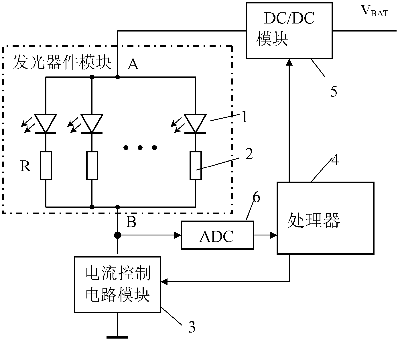
[0029] The brightness of the backlight of the terminal product is often adjustable, and several levels of brightness are set on the user interface for the user to set. On the hardware, the purpose of changing the brightness of the backlight is achieved by adjusting the current in the LED, and different brightness levels of the backlight correspond to different current levels. The greater the LED operating current, the higher the voltage across the LED; on the contrary, the smaller the LED operating current, the lower the voltage across the LED. The LED backlight circuit with DC / DC function in the prior art always provides a sufficiently high voltage, so that the voltage provided at low brightness levels will be much more plentiful, and these voltages will be consumed by the current control circuit, forming unnecessary heat loss.

[0030] The embodiment of the present invention is mainly aimed at a backlight circuit with a DC / DC function, and provides a backlight circuit witho...


PUM


Abstract

The invention provides a backlight circuit, and a method and a terminal for controlling the voltage of the backlight circuit. The backlight circuit comprises a luminescent device module, a current control circuit module, a switch power module and a processor, wherein the luminescent device module is serially connected with the current control circuit module; the switch power module provides voltage for the luminescent device module; the processor is used for controlling the output voltage of the switch power module in a backlight starting process, and enables the voltage of the current control circuit module to be equal to or slightly greater than the pre-stored corresponding reference voltage of the current control circuit module under the corresponding brightness level. The using voltage can be automatically controlled according to the backlight brightness level, backlight power consumption can be reduced to the maximum degree on the premise that the user experience is unaffected, so that the purpose of saving energy is achieved, and the endurance ability of the terminal is improved.

Description

technical field [0001] The invention relates to the technical field of terminal equipment, in particular to a backlight circuit, a method for controlling the voltage of the backlight circuit, and a terminal. Background technique [0002] LCD (liquid crystal display) has become an important part of entertainment terminal products and communication terminal products, and the brightness of LCD backlight has a great influence on the imaging effect. LED (Light Emitting Diode) is more and more used as a backlight light-emitting device due to its significant advantages of low power consumption and long life. Usually, a constant voltage or battery voltage is provided for the anode of the LED, and the cathode is a current control circuit module. The disadvantages of this circuit: if the anode provides a constant voltage, the efficiency of the backlight is very low at low brightness levels, and a considerable part of the power consumption is on the current control circuit module; if t...

Claims


Application Information

Patent Timeline
IPC IPC(8): G09G3/34G09G3/36
CPCG09G2330/026Y02B20/347G09G3/3406G09G2330/021G09G2320/0626H05B33/0815H05B45/3725Y02B20/30
Inventor 孙钦利魏红亮佘海波黄伟周仕霞
Owner ZTE CORP
Why Eureka
Try Eureka