Pixel driving circuit, display device and driving method thereof

A pixel driving circuit and driving method technology, applied to static indicators, instruments, etc., can solve the problems of poor display effect and abnormal display of light-emitting devices, and achieve the effect of avoiding abnormal display

Active Publication Date: 2016-03-23
BOE TECH GRP CO LTD +1
View PDF4 Cites 0 Cited by
  • Summary
  • Abstract
  • Description
  • Claims
  • Application Information

AI Technical Summary

Problems solved by technology

[0005] Embodiments of the present invention provide a pixel driving circuit, a display device and a driving method thereof, which solve the problem of poor display effect of light-emitting devices and occurrence of abnormal display when using the existing pixel driving circuit

Method used


Image

  • Pixel driving circuit, display device and driving method thereof
  • Pixel driving circuit, display device and driving method thereof
  • Pixel driving circuit, display device and driving method thereof

Examples


Embodiment Construction

[0026] The following will clearly and completely describe the technical solutions in the embodiments of the present invention with reference to the accompanying drawings in the embodiments of the present invention. Obviously, the described embodiments are only some, not all, embodiments of the present invention. Based on the embodiments of the present invention, all other embodiments obtained by persons of ordinary skill in the art without creative efforts fall within the protection scope of the present invention.

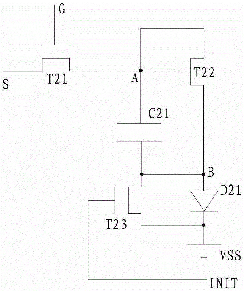
[0027] An embodiment of the present invention provides a pixel driving circuit, such as figure 2 As shown, it includes: a first transistor T21, a second transistor T22, a third transistor T23, a capacitor C21 and a light emitting device D21; the gate of the first transistor T21 is connected to the gate line G, the source is connected to the data line S, and the drain is connected to The gate and drain of the second transistor T22 and one end of the capacitor C21; ...


PUM


Abstract

The embodiment of the invention provides a pixel drive circuit, a display device and a drive method thereof, relating to the technical field of panel display, and solving the problems of poor display effect and abnormal display phenomenon of a luminescent device when the traditional pixel drive circuit is used. In the invention, because of the coordination of a first transistor and a capacitor or the coordination of the first transistor, a second transistor and the capacitor, in a threshold compensating state, a potential of one end of a capacitor is equal to a threshold voltage of the second transistor, and in a threshold acquiring stage, a threshold voltage of the second transistor is acquired through a data line, therefore, a sum of a to-be-displayed data voltage and the threshold voltage of the second transistor is provided to the data wire in a display stage, so that the size of current flowing through the luminescent device when being conducted is not influenced by the threshold drift of the second transistor, and abnormal display of the luminescent device is avoided.

Description

technical field [0001] The invention relates to the field of flat panel display technology, in particular to a pixel driving circuit, a display device and a driving method thereof. Background technique [0002] Traditional OLED (Organic Light-Emitting Diode, Organic Light-Emitting Diode) pixel drive circuit such as figure 1 As shown, it includes: a transistor T11, a transistor T12, a light emitting device D11 and a capacitor C11. The gate of the transistor T11 is connected to the signal scanning line SCAN, the source is connected to the data line DATA, and the drain is connected to the gate of the transistor T12; the drain of the transistor T12 is connected to the power line VDD, and the source is connected to the common ground terminal VSS through the light emitting device D11; Capacitor C11 is connected between the gate and source of transistor T12. [0003] figure 1 The working process of the OLED pixel driving circuit shown includes: configuration stage, when the sign...

Claims


Application Information

Patent Timeline
Patent Type & Authority Patents(China)
IPC IPC(8): G09G3/20G09G3/3233G09G3/3208
Inventor 郭瑞
Owner BOE TECH GRP CO LTD
Why Eureka
Try Eureka