Mobile robot separating visual positioning and navigation method and positioning and navigation system thereof

A technology of visual positioning and navigation methods, applied in control/adjustment systems, two-dimensional position/channel control, instruments and other directions, can solve problems such as troublesome wiring, cumbersome wiring, low efficiency, etc., to achieve convenient line change, accurate positioning and navigation , the effect of high efficiency

Inactive Publication Date: 2013-02-13
朱绍明
View PDF7 Cites 32 Cited by
  • Summary
  • Abstract
  • Description
  • Claims
  • Application Information

AI Technical Summary

Problems solved by technology

[0003] However, the positioning and navigation methods of the traditional mobile robot system are not flexible enough, the efficiency is low, the positioning and navigation is not accurate enough or the cost is high, etc.
Some of the above-mentioned problems exist in several traditional mobile robot systems: (1) low-voltage wires are laid in the field, and the sensors on the robot detect the conductive wires for boundary recognition, positioning and guidance, but this method is troublesome in wiring and complicated in work requires cumbersome wiring or can only use inefficient random scan method
This method is troublesome to install and reduces the overall efficiency
(3) Through laser ranging scanning, the site map is established by laser ranging scanning method, which is generally used for point-to-point operation and requires professional installation
Outdoors, low-resolution GPS can be used for initial positioning assistance, and the cost is relatively high
(4) Through color tracking, the running route is marked with a special color, and the camera or sensor on the robot navigates by recognizing the color. This method is similar to the low-voltage guidance method. When the path changes, the color code needs to be re-arranged, which is inefficient
No overall concept, possible duplication of work, low precision and low efficiency

Method used


Image

  • Mobile robot separating visual positioning and navigation method and positioning and navigation system thereof
  • Mobile robot separating visual positioning and navigation method and positioning and navigation system thereof
  • Mobile robot separating visual positioning and navigation method and positioning and navigation system thereof

Examples


Embodiment Construction

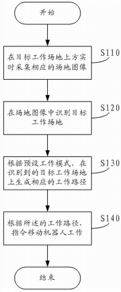
[0045] Such as figure 1 Shown, a kind of mobile robot separation vision positioning navigation method, comprises:

[0046] S110. Collect corresponding site images in real time above the target work site;

[0047] S120. Identify the target work site in the site image, including identifying the boundary and obstacles of the target work site;

[0048] Specifically, the range of the mobile robot's required operating site, that is, boundaries, obstacles, etc., can be set through automatic identification, human-computer interaction identification or manual identification.

[0049] Manuals can even set different types of boundaries or obstacles, and the mobile robot will handle them differently. For example, it can be set as ponds, bunkers, rockeries, trees, fences, etc. in lawn applications. When it is a pond or a bunker, sounding sensors or redundant vision positioning (that is, a margin) can be used to ensure that the robot does not fall. And rockery, trees, and fences can be ...


PUM


Abstract

A mobile robot separating visual positioning and navigation method and a positioning and navigation system of the mobile robot separating visual positioning and navigation method comprise that corresponding site images are collected in real time above a target work site. The target work site is recognized in the site images. The recognition of the target work site comprises the recognition of target work site boundaries and barriers. According to a preset working mode, a corresponding working path is generated on the recognized target work site. According to the working path, a mobile robot is instructed to work. The mobile robot separating visual positioning and navigation method and the positioning and navigation system of the mobile robot separating visual positioning and navigation method are high in efficiency, accurate in positioning and navigation and low in cost, and simultaneously can efficiently achieve a path patrol type application and a traversal scan type application.

Description

technical field [0001] The invention belongs to the technical field of mobile robots, and in particular relates to a separate visual positioning and navigation method for a mobile robot and a positioning and navigation system thereof. Background technique [0002] At present, some work on the workplace can be or has been done automatically by mobile robot systems, such as lawn mowing, agricultural use, snow removal in the gate, golf ball picking, indoor cleaning, factory material handling, etc. [0003] However, the positioning and navigation method of the traditional mobile robot system is not flexible enough, the efficiency is low, the positioning and navigation is not accurate enough, or the cost is high. Some of the above-mentioned problems exist in several traditional mobile robot systems: (1) low-voltage wires are laid in the field, and the sensors on the robot detect the conductive wires for boundary recognition, positioning and guidance, but this method is troublesom...

Claims


Application Information

Patent Timeline
IPC IPC(8): G05D1/02
CPCG05D1/0246G05D2201/0213
Inventor 朱绍明
Owner 朱绍明
Why Eureka
Try Eureka