Motive seal swivel joint for entrucking low-temperature LNG (liquefied natural gas)

A rotary joint and dynamic sealing technology, applied in the direction of pipes/pipe joints/fittings, flange connections, adjustable connections, etc., can solve problems such as splash leakage and achieve good sealing performance

Inactive Publication Date: 2013-02-13
JIANGSU CHANGLONG PETROCHEM EQUIP
View PDF4 Cites 3 Cited by
  • Summary
  • Abstract
  • Description
  • Claims
  • Application Information

AI Technical Summary

Problems solved by technology

The groove for installing the main sealing ring in the existing rotary joint is open. After the main sealing ring leaks in use, liquid LNG (liquefied natural gas) enters between the primary and secondary sealing rings. When the LNG returns to normal temperature, the expansion force Distorts the primary seal into the flow path, resulting in a larger splash leak on the second use

Method used


Image

  • Motive seal swivel joint for entrucking low-temperature LNG (liquefied natural gas)
  • Motive seal swivel joint for entrucking low-temperature LNG (liquefied natural gas)

Examples


Embodiment Construction

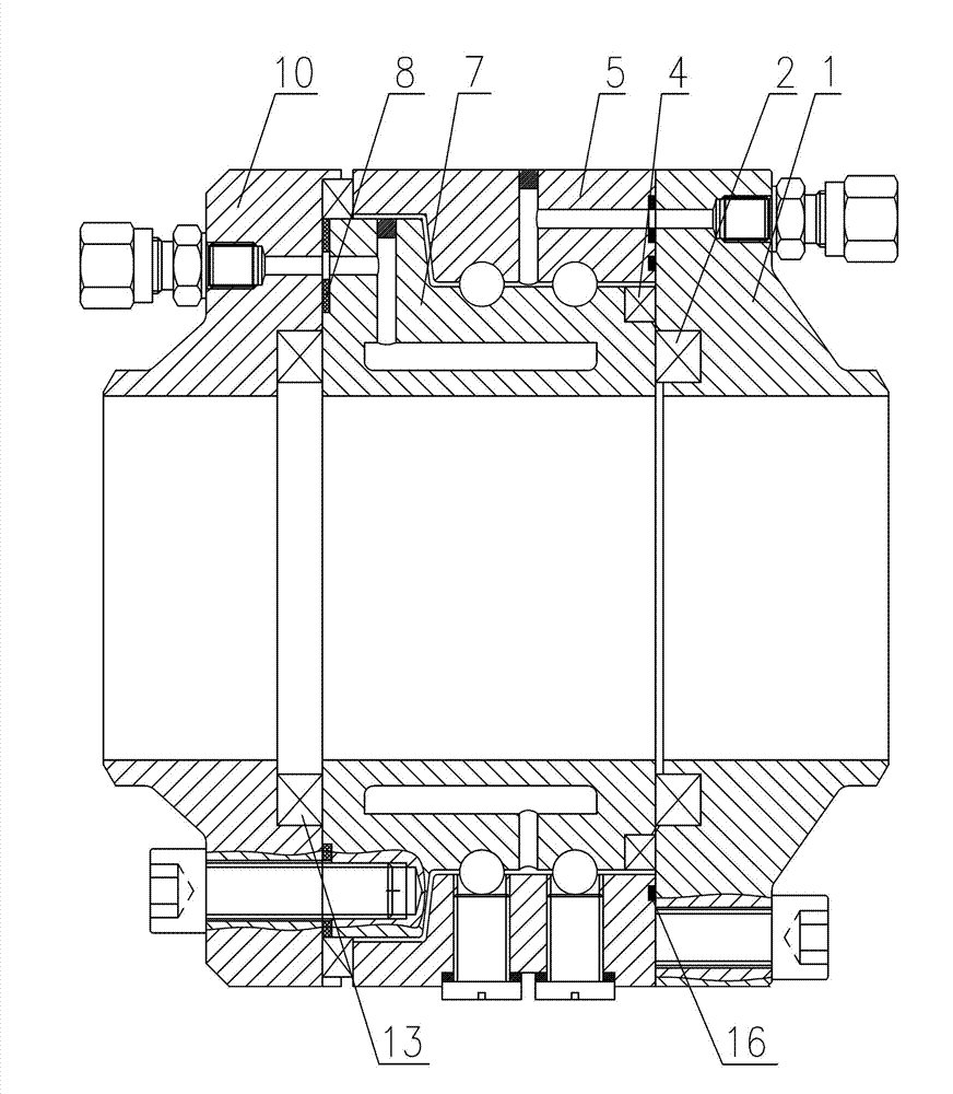
[0012] Specific embodiments of the present invention will be described in detail below in conjunction with the accompanying drawings.

[0013] Such as figure 2 As shown, the dynamic sealing rotary joint for low-temperature LNG loading according to the present invention comprises a left flange 10 and a right flange 1, the left flange 10 and the inner ring 7 are connected by screws to form a left rotating part, and the right flange 1 and the The outer ring 5 is connected with screws to form a right-hand rotation part, and the left-hand rotation part and the right-hand rotation part can rotate relatively.

[0014] The active sealing ring 2 is installed between the right side of the inner ring 7 and the active sealing ring groove provided on the left end surface of the right flange 1, and the active sealing ring groove provided on the left end surface of the right flange 1 has a function for preventing the active sealing ring 2 from sliding. stop mouth.

[0015] A spigot is add...


PUM


Abstract

The invention discloses a motive seal swivel joint for entrucking low-temperature LNG (liquefied natural gas), which is not easy to leak the LNG, and comprises a left flange and a right flange, wherein the left flange is connected with an inner ring to form a left rotating member; the right flange is connected with an outer ring to form a right rotating member; the left rotating member and the right rotating member can be relatively rotated; a driving sealing ring is arranged between driving sealing ring grooves arranged at the right side of the inner ring and the left end face of the right flange; and a seam allowance for stopping the slide of the driving sealing ring is arranged on the driving sealing ring groove arranged on the right flange left end face. The seam allowance is added at the driving sealing ring groove to be a semi-open groove so as to prevent that the leaked LNG can push the driving sealing ring to a runner after expansion, thereby avoiding the failure of sealing. The motive seal swivel joint has better sealing performance.

Description

technical field [0001] The invention relates to a dynamic sealing rotary joint for low-temperature LNG loading, which is mainly used as a rotary joint for crane pipes and oil delivery arms used in the fluid loading and unloading process in the petrochemical industry. Background technique [0002] Cryogenic crane tube is an industrial product that has only been developed in China in recent years, and is mainly used for loading and unloading cryogenic fluids in the petrochemical industry. The core component of its technology is a rotary joint. Currently, mainstream products in the domestic market such as figure 1 As shown, its main structural components are left flange, right flange, inner ring, outer ring and seals. The rationality of the structure of the rotary joint and the excellent design dimensions determine the sealing performance and operational performance of the rotary joint. The groove for installing the main sealing ring in the existing rotary joint is open. Afte...

Claims


Application Information

Patent Timeline
Patent Type & Authority Applications(China)
IPC IPC(8): F16L27/08F16L23/18
Inventor 冯是公
Owner JIANGSU CHANGLONG PETROCHEM EQUIP
Why Eureka
Try Eureka