
Reciprocating type tilting tray compressor structure

A swash plate compressor, reciprocating technology, applied in the direction of liquid variable capacity machinery, mechanical equipment, machines/engines, etc., can solve the problems of low compressor working efficiency and large driving resistance, and reduce the driving torque and reduce the Driving resistance, the effect of improving work efficiency

Active Publication Date: 2013-02-13
浙江威乐新能源压缩机有限公司
View PDF7 Cites 1 Cited by
  • Summary
  • Abstract
  • Description
  • Claims
  • Application Information

AI Technical Summary

Problems solved by technology

[0002] The reciprocating swash plate compressor has long dominated the market with a series of advantages such as compact structure, convenient installation, high reliability, low noise, and stable operation. However, the low working efficiency of this type of compressor has also become a technical problem that has been difficult to overcome for a long time in the industry. , mainly manifested in the presence of clearance in the cylinder and large driving resistance; how to reduce or eliminate the clearance has become a difficult problem to be solved at present

Method used


Image

  • Reciprocating type tilting tray compressor structure
  • Reciprocating type tilting tray compressor structure

Examples


Embodiment 1

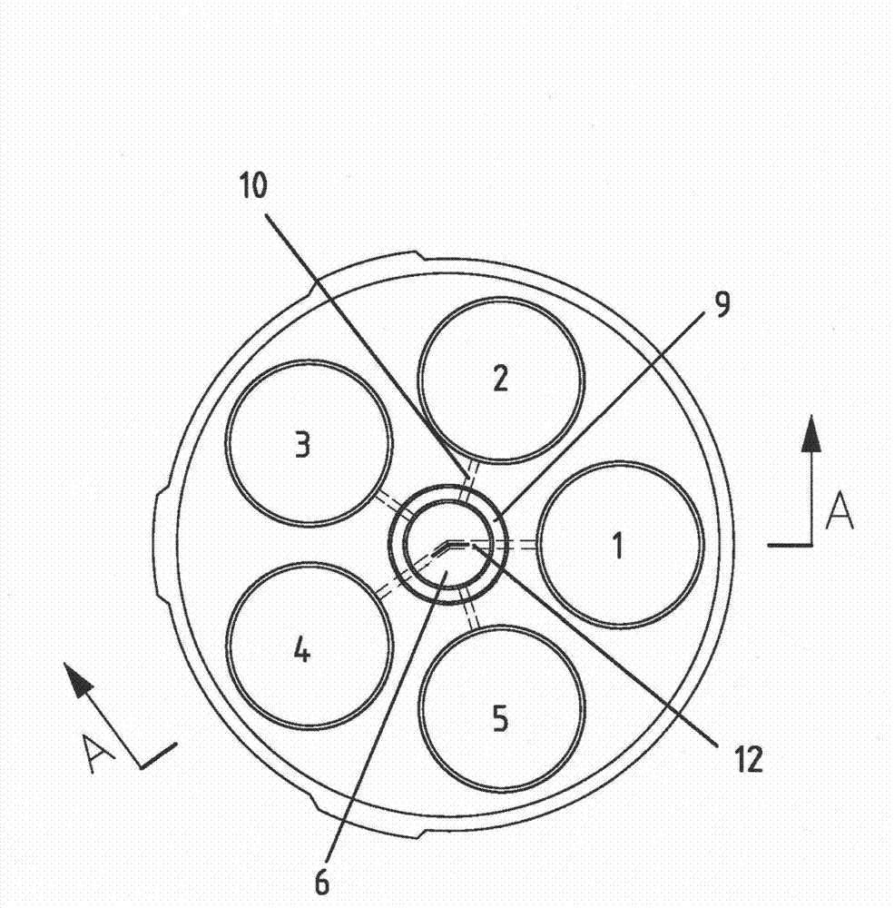
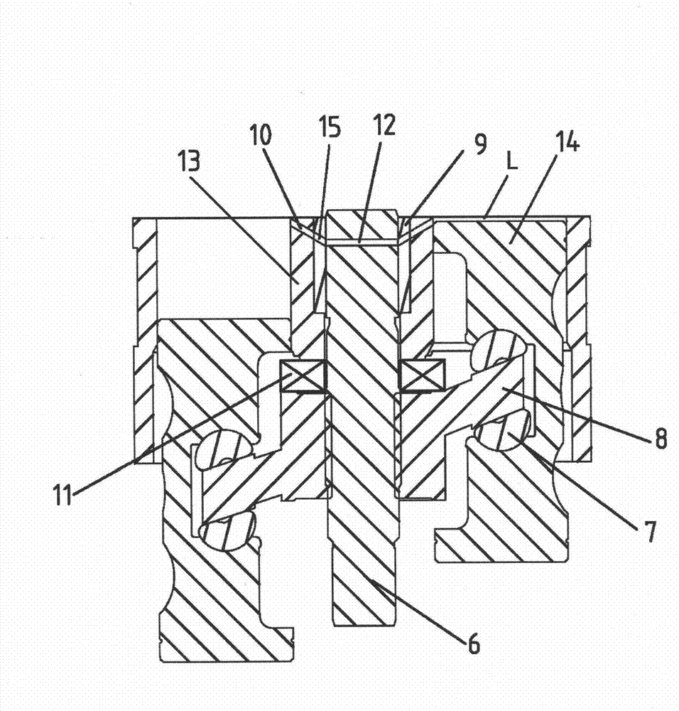
[0018] The present invention is a reciprocating swash plate compressor structure, such as figure 1 , figure 2 Shown is a structural schematic diagram of a reciprocating swash plate compressor structure. A main shaft 6 is installed in the center of the cylinder body 13, and the sealing shaft sleeve 9 is used to seal between the cylinder body 13 and the main shaft 6. The hemisphere 7 is connected with the piston 14, the main shaft 6 is provided with a main shaft ventilation hole 12, the cylinder body 13 is provided with a cylinder ventilation hole 10, and the sealing sleeve 9 is provided with a connection hole 15. Both ends of the main shaft air hole 12 are respectively connected with two adjacent connection holes 15 . The connecting hole 15 communicates with the cylinder vent hole 10 , and the cylinder vent hole 10 corresponds to the connecting hole 15 . The clearance L is located at the end face of the cylinder in the cylinder block 13 , and the clearance L communicates wi...

Embodiment 2

[0025] The present invention is a reciprocating swash plate compressor structure, the number of cylinders in the cylinder is 4 cylinders, the angle between the two sides of the main shaft vent hole is 180°, and the main shaft must be rotated 90° clockwise to connect the main shaft vent hole with the other The two cylinders are connected. Others are the same as in Example 1.


PUM


Abstract

The invention discloses a reciprocating type tilting tray compressor structure which comprises a cylinder body, wherein the cylinder body is internally provided with a main shaft; a sealing shaft sleeve is arranged between the cylinder body and the main shaft, the main shaft is connected with a bearing, the main shaft is provided with a tilting tray connected with the bearing, and the tilting tray is connected with a piston through a hemisphere. The reciprocating type tilting tray compressor structure is characterized in that the main shaft is provided with a main shaft air vent, the cylinder body is provided with an air cylinder air vent, and the sealing shaft sleeve is provided with a connecting hole. The reciprocating type tilting tray compressor structure provided by the invention has the characteristics that the driving torque of a compressor is small, the driving resisting force is small, and the operational efficiency is high and the like.

Description

technical field [0001] The invention relates to a structure of a reciprocating swash plate compressor, which belongs to the field of swash plate compressors. Background technique [0002] The reciprocating swash plate compressor has long dominated the market with a series of advantages such as compact structure, convenient installation, high reliability, low noise, and stable operation. However, the low working efficiency of this type of compressor has also become a technical problem that has been difficult to overcome for a long time in the industry. , mainly manifested in the existence of clearance in the cylinder, and the driving resistance is large; how to reduce or eliminate the clearance has become a difficult problem to be solved at present. Contents of the invention [0003] The purpose of the present invention is to solve the problem of how to reduce or eliminate the clearance and reduce the driving resistance, and provide a reciprocating swash plate compressor st...

Claims


Application Information

Patent Timeline
Patent Type & Authority Applications(China)
IPC IPC(8): F04B27/12
Inventor 卢辉
Owner 浙江威乐新能源压缩机有限公司
Learn More