
Grinding fixture

A grinding jig and a technology to be ground, which is applied in the field of mechanical processing, can solve the problems of low automation, achieve the effects of reducing labor intensity, improving production efficiency, and reducing non-working time

Active Publication Date: 2015-04-29
SHENZHEN SHENLAN PRECISION MACHINERY
View PDF6 Cites 0 Cited by
  • Summary
  • Abstract
  • Description
  • Claims
  • Application Information

AI Technical Summary

Problems solved by technology

[0003] The object of the present invention is to provide a grinding fixture, which aims to solve the problem of low automation in the prior art that requires workers to clamp and position the same workpiece to be ground multiple times

Method used


Image

  • Grinding fixture
  • Grinding fixture
  • Grinding fixture

Examples


Embodiment Construction

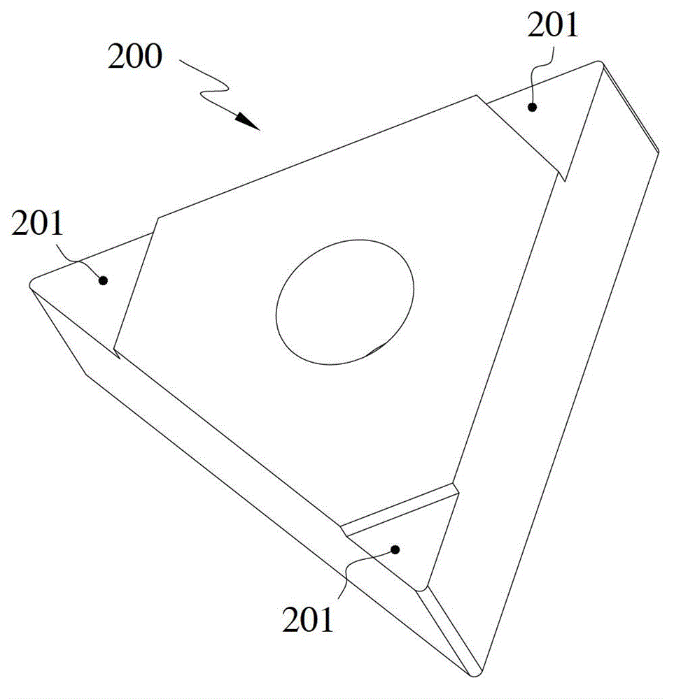
[0027] In order to make the object, technical solution and advantages of the present invention clearer, the present invention will be further described in detail below in conjunction with the accompanying drawings and embodiments. It should be understood that the specific embodiments described here are only used to explain the present invention, not to limit the present invention.

[0028] The implementation of the present invention will be described in detail below in conjunction with specific drawings.

[0029] Such as figure 1 As shown, the workpiece 200 to be ground in the embodiment of the present invention has a triangular shape, and three pointed planes 201 distributed along its circumference need to be ground. It is easy to understand that this place is not limited to the workpiece to be ground in a triangular shape, To process diamond-shaped parts, as long as the surfaces to be ground are distributed circumferentially.

[0030] see figure 2 As shown, the grinding...


PUM


Abstract

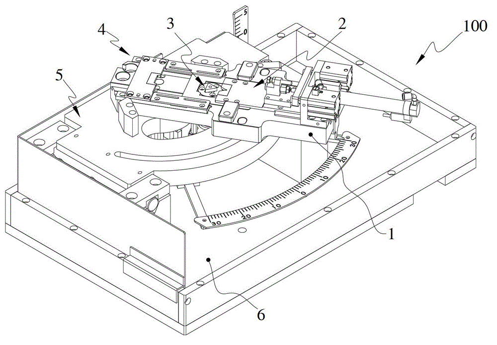
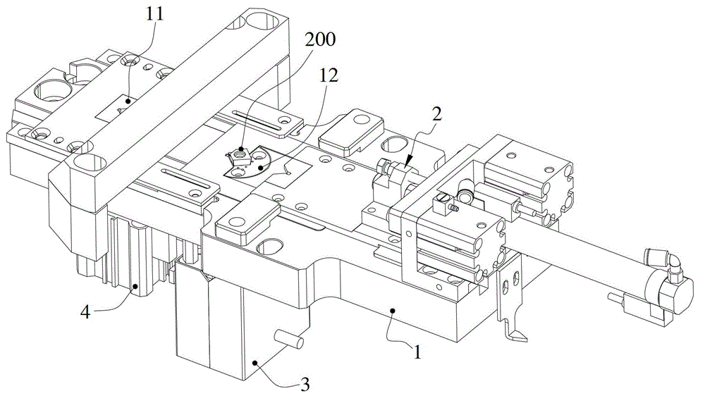
The invention belongs to the technical field of machining and particularly relates to a grinding fixture. The grinding fixture comprises a bearing plate, a pushing and pulling assembly, an abutting assembly, a rotation assembly and a controller, wherein one end of the bearing plate is provided with a grinding station used for grinding workpieces, a rotation station which can rotate the workpieces to be ground is arranged at the position close to the middle of the bearing plate, the pushing and pulling assembly is arranged on the bearing plate, can enable the workpieces to be ground to reciprocate between the grinding station and the rotation station and can enable the workpieces to be ground to horizontally and tightly abut against the grinding station, the abutting assembly can vertically abut the workpieces to be ground against the grinding station, the rotation assembly is arranged below the rotation station and can rotate the workpieces to be ground, and the controller is used for controlling the pushing and pulling assembly, the abutting assembly and the rotation assembly to orderly move. According to the grinding fixture, automation is achieved during the whole process, and workers are not required for repeatedly installing fixtures to position the same workpiece to be ground, so that labor intensity of workers is reduced, non-operational time of the device is reduced, and production efficiencies are improved.

Description

technical field [0001] The invention belongs to the technical field of mechanical processing, and in particular relates to a grinding fixture. Background technique [0002] In actual production, it is often necessary to grind multiple characteristic surfaces distributed circumferentially on some small parts, such as Figure 11 As shown, the workpiece 200 to be ground is in a triangular shape, and it is necessary to grind three pointed planes 201 distributed along its circumference. The tip plane 201 distributed in the circumferential direction, after the completion, the worker takes off the part to be ground, rotates it at an angle, and then re-clamps and grinds another tip plane 201, and repeats this until the workpiece 200 is ground. All the tip planes 201 distributed in the circumferential direction have been ground. In this way, the degree of automation is low. Grinding a part requires workers to manually clamp multiple times. The labor intensity of the workers is high, ...

Claims


Application Information

Patent Timeline
Patent Type & Authority Patents(China)
IPC IPC(8): B24B37/27
Inventor 郑青焕
Owner SHENZHEN SHENLAN PRECISION MACHINERY
Learn More