
mobility aids

A technology of moving assist and moving body, applied in multi-purpose hand tools, switches with brakes, applications, etc., can solve problems such as position restrictions, eliminate the possibility of buffering, and improve the effect of operating characteristics

Inactive Publication Date: 2015-09-02
NIFCO INC
View PDF11 Cites 0 Cited by
  • Summary
  • Abstract
  • Description
  • Claims
  • Application Information

AI Technical Summary

Problems solved by technology

[0003] In the buffer closure device mentioned above, when the latch 5 is in the standby position as shown in FIG. Accumulated force while its position is constrained

Method used


Image

  • mobility aids
  • mobility aids
  • mobility aids

Examples


Embodiment Construction

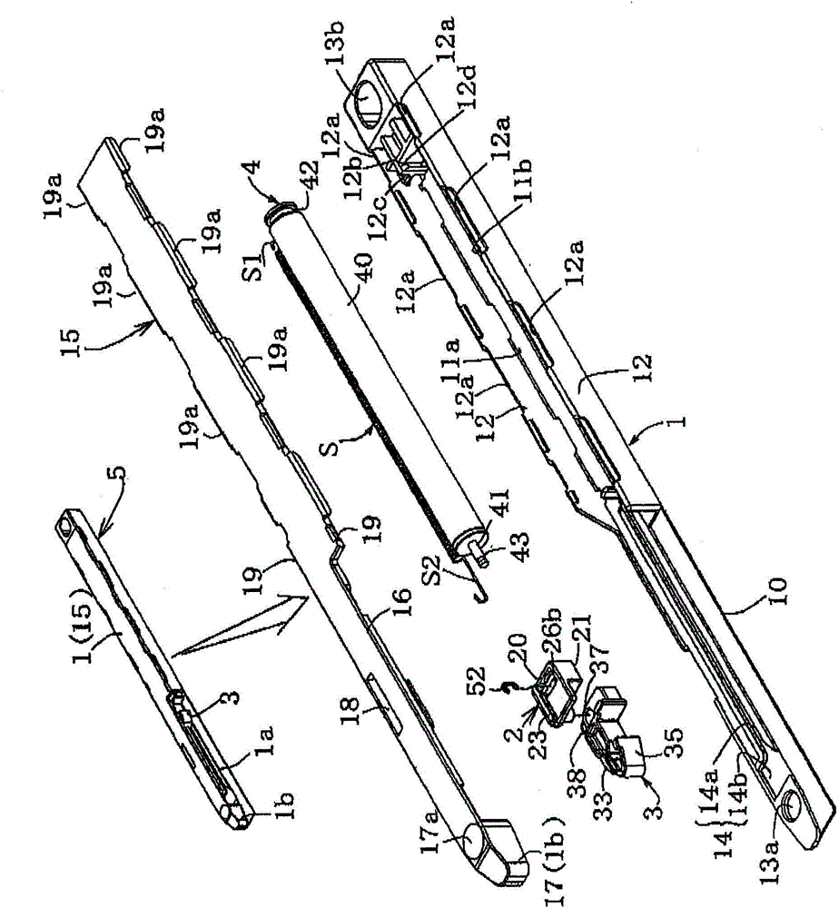
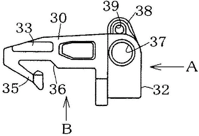
[0062] Embodiments of the present invention will be described with reference to the drawings. Figure 1(a) to Figure 9(c) represents the first embodiment of the present invention, Figure 10(a) to Figure 13(b) The second embodiment of the present invention is shown. In the following description, the main parts of the first embodiment, the drawer, the sliding door, the striker, the receiving member, the light shielding member, the operation, the modified points of the second embodiment, and the order of operation are described in detail. In addition, in the drawings, some structures are simplified or omitted due to drawing restrictions.

[0063] (main parts of the first embodiment)

[0064] The movement assisting device of the first embodiment is constituted by a drawer 5 and a striker 6 so that a sliding door 50 as an example of a movable body is between an open position and a closed position on a main body frame 9 as an example of a fixed body. In the movable structure, es...


PUM


Abstract

A movement assist device includes a retraction tool having a case, a latch switched between a standby position which is locked inside the case and a retraction position which releases the locking so as to be capable of sliding, and an urging device; and a striker switching the latch from the standby position to the retraction position, or vise versa. The retraction tool or the striker is provided in a fixed body, or a moving body movably disposed in the fixed body. When the latch is switched from the standby position to the retraction position, a sliding door moves by an urging force. The case includes a striker leading portion notched such that a width of the case becomes thin to a middle of the other end from one end in a longitudinal direction. Also, one portion of the latch is exposed and disposed in the leading portion.

Description

technical field [0001] The present invention relates to a movement assisting device for switching a moving body to a closed position or an open position, or a storage position or a pull-out position by using an active force during operation. In addition, the target movement assisting device is also referred to as a slide assisting device, a buffer sealing device, or the like. Background technique [0002] Figure 14(a) to Figure 14(c) It shows the buffer closure device disclosed by patent document 1. Symbol F is an upper frame constituting a main body frame as a fixed body. A horizontal groove is provided on the upper frame F. The sliding door D as a movable body has a tenon D1 fitted into the horizontal groove. Also, in this structure, a drawer (apparatus main body) 1 is provided on the sliding door D, and a striker (fitting member) 2 is attached to the lateral groove of the upper frame F. As shown in FIG. The striker 2 is installed in the transverse groove of the upper...

Claims


Application Information

Patent Timeline
Patent Type & Authority Patents(China)
IPC IPC(8): E05F1/16E05C21/00E05F5/02
CPCY10T16/61A47B88/047E05Y2900/20E05F1/16E05Y2800/24Y10T16/56Y10T16/27Y10T16/593E05F5/003A47B88/467E05Y2201/10
Inventor 清水洋兵
Owner NIFCO INC
Learn More