Cable pay-off device

A pay-off device and cable technology, applied in the direction of overhead line/cable equipment, etc., can solve the problems of labor and low efficiency, and achieve the effects of simple structure, high pay-off efficiency, and reduced labor intensity.

Inactive Publication Date: 2013-02-06
高密胜鑫交通工程有限公司
View PDF0 Cites 4 Cited by
  • Summary
  • Abstract
  • Description
  • Claims
  • Application Information

AI Technical Summary

Problems solved by technology

Since the cable is far away from the insulator after being pulled up, it is still necessary to manually pull the cable further, which is not only laborious, but also less efficient

Method used


Image

  • Cable pay-off device
  • Cable pay-off device
  • Cable pay-off device

Examples


Embodiment Construction

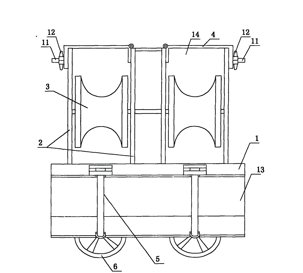
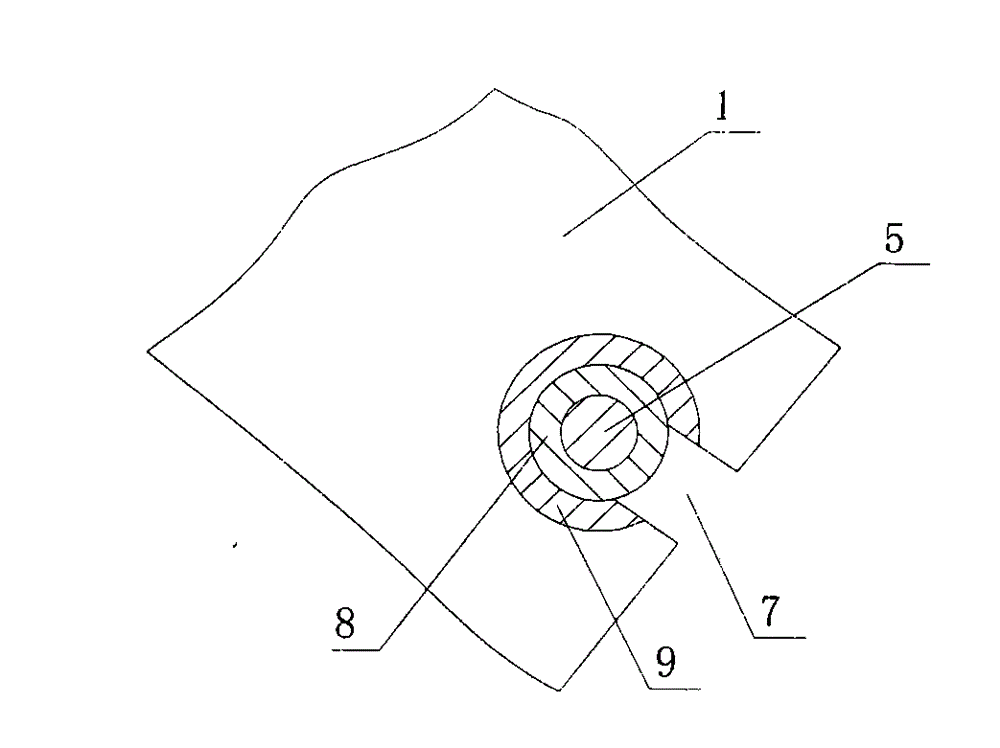
[0014] Such as figure 1 and figure 2 The shown cable pay-off device includes a bracket 1 for clamping on the cable rack of the wire rod. The bracket 1 is provided with a bayonet 13 and a locking mechanism. The bolt 5 and the handwheel 6 screwed on the bolt 5 have a gap 7 for the bolt 5 to go in and out on the other edge of the bayonet. The bayonet 13 is used for the insertion of the cable rack, that is, the bracket 1 is inserted into the cable rack through the bayonet 13; after the bracket 1 wraps the cable rack, turn the bolt 5 into the gap 7, and then turn the handwheel 6 to The locking of the bracket 1 on the cable rack can be realized. The support 1 is fixedly connected with the wire wheel frame 2 with the opening 14 at the outer end, the wire wheel frame 2 is rotatably connected with a wire wheel 3 corresponding to the opening 14 of the frame 1, and the frame 1 is hinged with a cable capable of closing the opening. The guard plate 4, the reel frame 2 and the cable gua...


PUM


Abstract

The invention discloses a cable pay-off device. The device comprises a bracket, wherein the bracket can be clamped on a cable bracket through locking mechanisms arranged on the bracket; the bracket is fixedly connected with reel frames at the outer ends of which openings are formed; the reel frames are rotationally connected with reels corresponding to the openings of the bracket in position; cable protecting sheets capable of sealing the openings are hinged on the bracket; and the locking mechanisms capable of locking the cable protecting sheets are respectively arranged on the reel frames and the cable protecting sheets. The cable pay-off device is simple in structure and high in pay-off efficiency, and can effectively reduce the labor intensity.

Description

technical field [0001] The invention relates to a tool for erecting cables on a wire rod, in particular to a wire-laying device. Background technique [0002] Regardless of the city or the country, the transmission of electricity is mostly done through cables supported on utility poles. A cable support is fixedly connected to the pole, an insulator is fixedly connected to the cable support, and cables are bound on the insulator. The process of bundling cables on insulators is commonly known as setting out. At present, the cable is guided by the guide wheels hanging on the cable bracket, and the cable is pulled up mechanically, and then the workers bind the cable on the insulator. Since the cable is far away from the insulator after being pulled up, it is still necessary to further pull the cable manually, which is not only laborious, but also less efficient. Contents of the invention [0003] The technical problem to be solved by the present invention is to provide a ca...

Claims


Application Information

Patent Timeline
Patent Type & Authority Applications(China)
IPC IPC(8): H02G1/02
Inventor 冷延敏
Owner 高密胜鑫交通工程有限公司
Why Eureka
Try Eureka