
Specially-shaped body annular groove machining mechanism

A processing mechanism and special-shaped technology, which is applied in the direction of metal processing machinery parts, metal processing equipment, manufacturing tools, etc., can solve the problems of equipment costs, tool costs, labor costs, difficulty in meeting design requirements, and long production and processing cycles. Improve processing quality and stability, improve processing efficiency, and reduce auxiliary time

Active Publication Date: 2013-02-06
TENGXUAN TECH
View PDF6 Cites 8 Cited by
  • Summary
  • Abstract
  • Description
  • Claims
  • Application Information

AI Technical Summary

Problems solved by technology

If the profiling or forming tools are used with special fixtures on ordinary machine tools, such processing methods will easily lead to unstable quality and it is difficult to meet the design requirements.
At present, the more advanced processing method is to use special fixtures on CNC boring machines, four-axis and five-axis machining centers, compile CNC programs, and use forming tools to complete the processing of holes and ring grooves. Although this can meet the design requirements, the installation Complex clamping, difficult calibration, and long production and processing cycles lead to a significant increase in equipment costs, tool costs, and labor costs

Method used


Image

  • Specially-shaped body annular groove machining mechanism

Examples


Embodiment Construction

[0015] The present invention will be further described below in conjunction with specific drawings and embodiments.

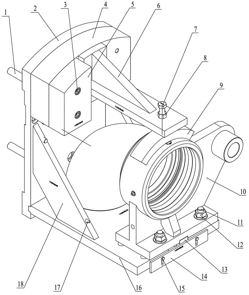
[0016] As shown in the figure: the special-shaped ring groove processing mechanism in the embodiment is mainly composed of a connecting bolt 1, a vertical plate 2, a screw 3, a counterweight 4, an adjustment block 5, a pressure plate 6, a compression screw 7, a lock nut 8, Briquetting block 9, special-shaped body to be processed 10, fastening screw 11, hex nut 12, positioning key 13, baffle plate 14, bolt 15, base plate 16, screw 17 and reinforcing plate 18 are composed of components.

[0017] like figure 1 As shown, the vertical plate 2 is provided with positioning grooves, and the base plate 16 is combined with the vertical plate 2 through the positioning grooves; connecting bolts 1 are installed on the vertical plate 2, and the vertical plate 2 is connected to the vertical plate by several connecting bolts 1. The chuck of the rotary spindle of the CNC lath...


PUM


Abstract

The invention relates to a specially-shaped body annular groove machining mechanism, which is characterized in that a vertical plate is connected with a soleplate into a whole, the vertical plate is provided with a connecting bolt which is in fitting connection with a numerical-control lathe rotary main shaft chuck to be locked; a specially-shaped body to be machined is tightened onto the soleplate through a tightening screw and a hexagonal nut, and the soleplate is provided with a positioning key which enables the specially-shaped body to be machined to rotate concentrically with the numerical-control lathe rotary main shaft; and a pressure plate is installed on the upper part of the vertical plate, the front end of the pressure plate is provided with a pressure block for compressing the specially-shaped body to be machined through a compression screw, the pressure block can be compressed onto the specially-shaped body to be machined by screwing the compression screw, and the compression screw is provided with a locking nut. A machined part of the specially-shaped body can be rotated through rapid installation, clamping and positioning, and an ordinary tool is used for cutting a hole and an annular groove to be machined of the specially-shaped body, so that the auxiliary time is reduced, the machining efficiency is improved, and the investment cost of the equipment and forming tool can be greatly reduced.

Description

technical field [0001] The invention relates to a special-shaped ring groove processing mechanism, which belongs to the technical field of mechanical processing equipment. Background technique [0002] The special-shaped body is an important part of the rotary joint. During the manufacturing process of the rotary joint, the machining of the special-shaped ring groove is completed by metal cutting. For example, using profiling or forming tools with special fixtures on ordinary machine tools to complete, such processing methods will easily lead to unstable quality and it is difficult to meet the design requirements. At present, the more advanced processing method is to use special fixtures on CNC boring machines, four-axis and five-axis machining centers, compile CNC programs, and use forming tools to complete the processing of holes and ring grooves. Although this can meet the design requirements, the installation The clamping is complicated, the calibration is difficult, an...

Claims


Application Information

Patent Timeline
Patent Type & Authority Applications(China)
IPC IPC(8): B23Q3/00B23Q11/00
Inventor 丁飏季新金孝班
Owner TENGXUAN TECH
Learn More