Fiber laser and control method and system
A fiber laser and light wave technology, applied in the field of communication, can solve the problems of long adjustment time and small adjustable range, and achieve the effect of short time, large adjustable range and convenient wavelength adjustment
- Summary
- Abstract
- Description
- Claims
- Application Information
AI Technical Summary
Problems solved by technology
Method used
Image

Examples
Embodiment 1
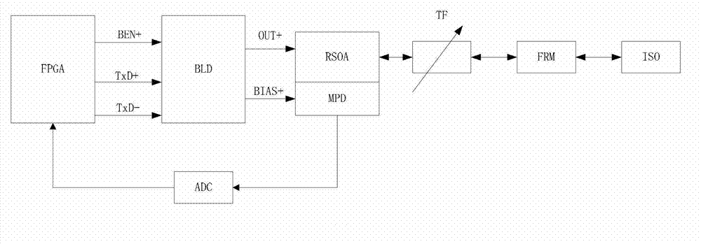
[0029] Such as figure 2 As shown, the present embodiment provides a fiber laser, which includes:
[0030] FPGA (Field-Programmable Gate Array, logic circuit), BLD (Burst Laser Driver, optical gain medium driver) and oscillator cavity;
[0031] Wherein, the FPGA is connected with the optical gain medium driver, and is used to obtain the first time according to the real-time temperature of the optical gain medium in the oscillation cavity and the first output power of the optical pulse to be emitted, and to control the light wave in the first time by using the BLD. The preset first wavelength oscillates in the oscillation cavity so that the light pulse reaches the first output power; when the first time is reached, the oscillation cavity is controlled by the BLD, and the wavelength obtained by the oscillation of the oscillation cavity is emitted to be the preset first output power. The wavelength and the output power are optical pulses with the first output power;
[0032] Th...
Embodiment 2
[0045] This embodiment provides a method for controlling a fiber laser. Under the control of the method, the fiber laser can generate an optical pulse with an adjustable wavelength, and the power of the optical pulse can be controlled. In this embodiment, the control of the fiber laser described in Embodiment 1 is taken as an example for illustration, and the fiber controller includes an FPGA, a BLD and an oscillation cavity.
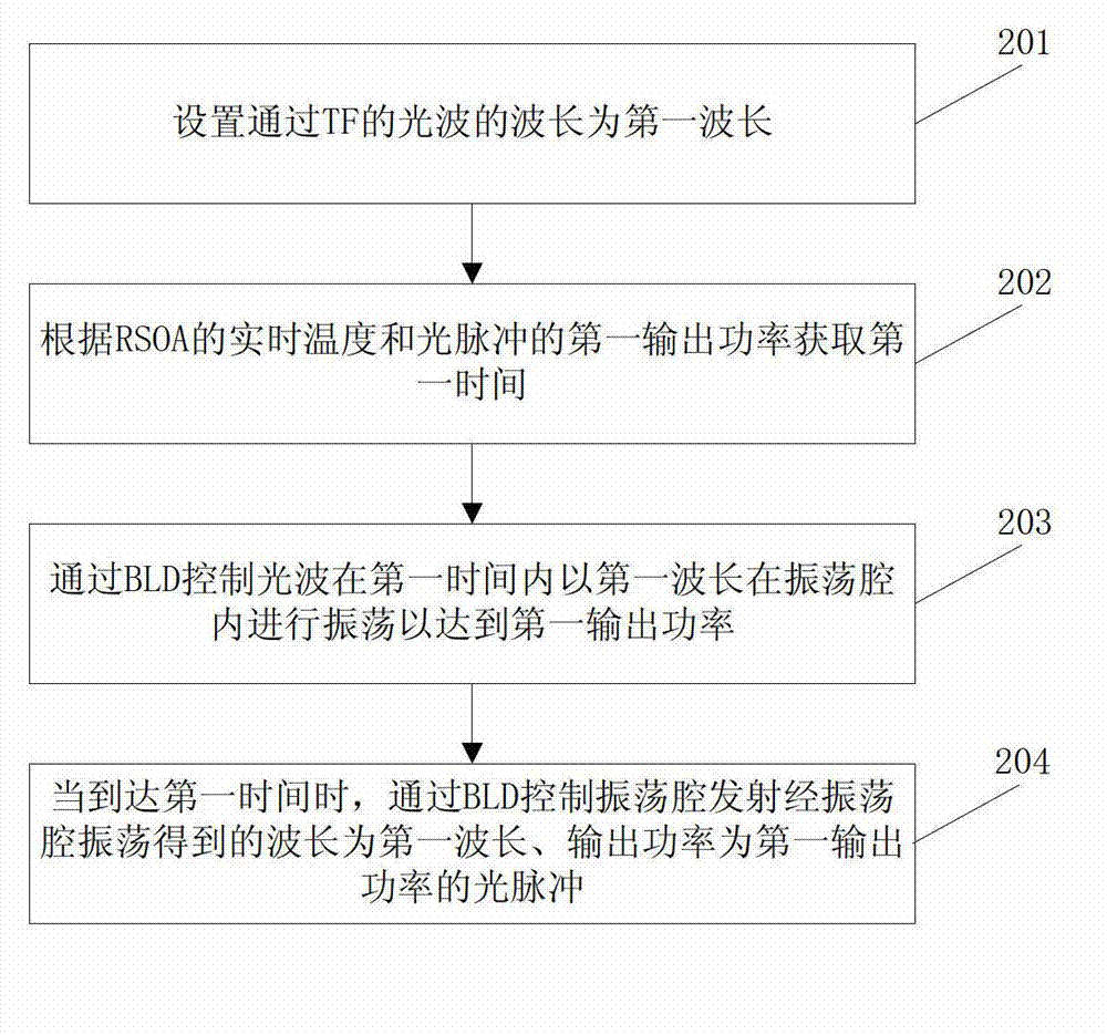
[0046] Such as image 3As shown, a control method of an optical fiber controller includes the following steps:
[0047] 201. Set the wavelength of the light wave passing through the TF as the first wavelength;
[0048] Wherein, the first wavelength is the wavelength of the light pulse to be emitted, or the wavelength of the light wave passing through the TF through the FPGA.
[0049] 202. Acquire the first time according to the real-time temperature of the RSOA and the first output power of the optical pulse;
[0050] Wherein, the first time specific...
Embodiment 3
[0076] Such as Figure 5 As shown, this embodiment provides a control system for a fiber laser. The fiber laser in this embodiment includes a BLD and an oscillating cavity. The system can be implemented specifically through an FPGA. The system includes:
[0077] A time acquisition module 301, configured to acquire the first time according to the real-time temperature of the optical gain medium in the oscillation cavity and the first output power of the optical pulse to be emitted;
[0078] The first control module 302 is configured to control the light wave to oscillate in the oscillation cavity at a preset first wavelength within the first time through the BLD, so that the light pulse reaches the first output power;
[0079] The second control module 303 is configured to control the oscillation cavity through the BLD to emit an optical pulse with a preset first wavelength and an output power of the first output power obtained through oscillation of the oscillation cavity when...
PUM
 Abstract
Description
Claims
Application Information
 - Generate Ideas
- Intellectual Property
- Life Sciences
- Materials
- Tech Scout
- Unparalleled Data Quality
- Higher Quality Content
- 60% Fewer Hallucinations
Browse by: Latest US Patents, China's latest patents, Technical Efficacy Thesaurus, Application Domain, Technology Topic, Popular Technical Reports.
© 2025 PatSnap. All rights reserved.Legal|Privacy policy|Modern Slavery Act Transparency Statement|Sitemap|About US| Contact US: help@patsnap.com