Inductive power supply and detection method of metallic foreign body thereof

An inductive power supply and metal foreign object technology, applied in instruments, scientific instruments, electric/magnetic exploration, etc., can solve problems such as difficulty in correct identification, inability of current detection circuit to accurately measure power changes, lack of flexibility in design, etc.

Active Publication Date: 2013-01-30
FU TONG TECH
View PDF8 Cites 25 Cited by
  • Summary
  • Abstract
  • Description
  • Claims
  • Application Information

AI Technical Summary

Problems solved by technology

However, the power loss is not only caused by metal foreign objects. When the relative position of the power supply coil and the power receiving coil is shifted, the power loss will also increase. Therefore, the technology of this invention needs to first define the transmission / reception coil and other power conversion components. Power loss data, or the power loss data corresponding to all possible metal foreign objects measured in advance as a basis for judgment, and then compared according to the actual power loss changes detected during operation
However, it is still necessary to default the settings of different parameters such as driving voltage, component characteristics, and coil specifications before performing this method. If the above-mentioned default parameters are changed during use, it will need to be reset, which makes the design of this method inflexible. It is difficult to correctly judge whether there is abnormal metal
In addition, this method still needs to install a current detection circuit at the power supply end and the power receiving end to calculate the value of current and voltage to measure the power change of the power supply end and the power receiving end, but the above current detection circuit may not be able to accurately measure Measure the actual power consumption changes, and the power changes at the receiving end also need to be transmitted to the power supply end through wireless signal transmission for calculation. Whether the signal transmission can be completed synchronously for subsequent calculations may also cause errors and cannot be accurately judged Whether there are metal foreign objects

Method used


Image

  • Inductive power supply and detection method of metallic foreign body thereof
  • Inductive power supply and detection method of metallic foreign body thereof
  • Inductive power supply and detection method of metallic foreign body thereof

Examples


Embodiment Construction

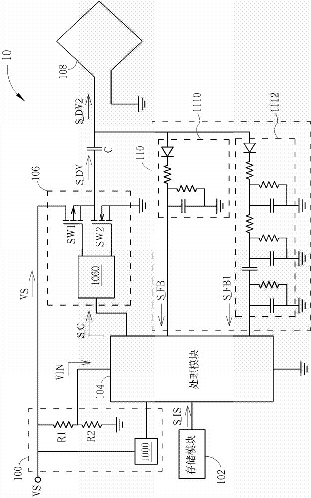
[0057] Please refer to figure 1 , figure 1 It is a schematic diagram of an inductive power supply 10 according to an embodiment of the present invention. Such as figure 1 As shown, the inductive power supply 10 includes an input power module 100 , a storage module 102 , a processing module 104 , a driving module 106 , an induction coil 108 and a feedback module 110 . In detail, the input power module 100 is coupled to the processing module 104 and the driving module 106 and receives a stable voltage source VS, and then divides the voltage through the resistors R1 and R2 to convert the stable voltage source VS into a lower voltage VIN is sent to the processing module 104 as a reference for subsequent work, and directly provides the stable voltage source VS to the drive module 106. At the same time, a receiving unit 1000 of the input power module 100 converts the stable voltage source VS to the processing module 104 as power used. The storage module 102 includes an initial s...


PUM


Abstract

The invention discloses an inductive power supply used for transmitting the inductive power and detecting whether a metallic foreign body exists. The inductive power supply comprises a processing module for generating a control signal in accordance with a default data and a feedback signal; a drive module for converting a stable voltage source to a drive voltage in accordance with the control signal; an induction coil for electrically transferring the drive voltage for the induction power transmission; and a feedback module for generating the feedback signal in accordance with the drive voltage received by the induction coil, wherein the default data is an initial state of the inductive power supply and a sine wave amplitude corresponding to the drive voltage containing the initial state, and the metallic foreign body influence a sine wave amplitude corresponding to the feedback signal.

Description

technical field [0001] The present invention relates to an inductive power supply and a metal foreign object detection method thereof, in particular to an inductive power supply capable of performing an inductive power transmission and detecting whether there is a metal foreign object at the same time and a metal foreign object detection method thereof . Background technique [0002] In the known art, the most important problem related to electromagnetic induction power system is that it must be able to adaptively identify a rechargeable device placed on a transmitter coil waiting for the operation of inductive power transfer, in which the operation similar to that of an induction cooker for cooking will be used The principle is to generate high-power electromagnetic wave energy for inductive power transmission. During the working process, when the high-power electromagnetic wave energy is received by a foreign metal, the foreign metal will be heated due to the electromagne...

Claims


Application Information

Patent Timeline
Patent Type & Authority Applications(China)
IPC IPC(8): H02M9/04G01V3/11
Inventor 蔡明球詹其哲
Owner FU TONG TECH
Why Eureka
Try Eureka