
Tightening device of insulator replacement device

A tensioner and insulator technology, applied in the direction of overhead lines/cable equipment, etc.

Active Publication Date: 2013-01-30
CHANGZHOU POWER SUPPLY OF JIANGSU ELECTRIC POWER +2
View PDF6 Cites 5 Cited by
  • Summary
  • Abstract
  • Description
  • Claims
  • Application Information

AI Technical Summary

Problems solved by technology

When the insulator replacement device is in use, it needs to withstand the tension in the line, and the rotation of the screw rod requires a large torque. Currently, the rotation of the screw rod is manual, so the operation is laborious and inconvenient

Method used


Image

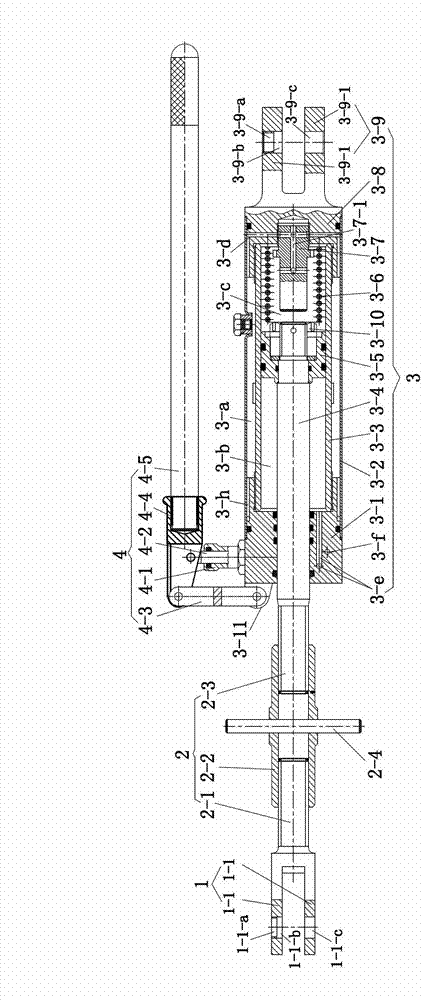
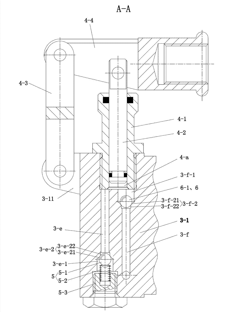
  • Tightening device of insulator replacement device
  • Tightening device of insulator replacement device
  • Tightening device of insulator replacement device

Examples


Embodiment 1

[0025] attached Figures 1 to 4 The tensioner shown includes a yoke 1 , a screw 2 and a hydraulic device 3 . The screw 2 is composed of No. Ⅰ screw 2-1, No. Ⅱ screw 2-3 and double-ended screw sleeve 2-2, and the double-ended screw sleeve 2-2 is connected to the Ⅰ screw 2-1 and the Ⅱ screw. Between 2-3, the thread directions of No. I screw mandrel 2-1 and No. II screw mandrel 2-3 are opposite, and a wrench 2-4 is fixed at the middle part of the double-ended screw sleeve 2-2. The fork joint 1 is connected to the end of No. 1 screw rod 2-1, the piston rod 3-4 of the hydraulic device 3 protrudes from the front end of the cylinder, and the No. 2 screw rod 2-3 is fixedly connected to the piston rod 3-4. It can be integrally processed by No. Ⅱ screw rod 2-3 and piston rod 3-4. The cylinder rear side of the hydraulic device 3 is a fork 3-9, and the hydraulic device 3 is connected with a hand pump 4.

[0026] The cylinder body of hydraulic device 3 is made up of front cylinder body ...


PUM


Abstract

The invention provides tightening device of an insulator replacement device. The tightening device comprises a forked joint, a screw rod and a hydraulic device, wherein the screw rod consists of a screw rod I, a screw rod II and a double-ended screw sleeve connected between the screw rod I and the screw rod II, wherein the middle of the double-ended screw sleeve is connected with a spanner; the forked joint is connected to the terminal of the screw rod I; the piston rod of the hydraulic device stretches out from the front end of a cylinder body and is fixedly connected with the screw rod II; the rear side of the cylinder body of the hydraulic device is a forked part; and the hydraulic device is connected with a stirrup pump. The tightening device adopts a screw rod and hydraulic device combined structure; the spanner is utilized to rotate the double-ended screw sleeve to adjust the length of the screw rods, so as to pre-absorb redundant stroke; then the hydraulic device provides effective working stroke, not only can the portability of the screw rods during an unstressed state and a slightly stressed state be utilized, but also the hydraulic device is utilized to complete the tightening operation under a rated working load by virtue of a smaller operating force, and the operation is labor-saving and convenient. The hydraulic device adopts a one-way throttle valve to automatically control the return oil flow, and the stroke fine adjustment of the hydraulic device is realized.

Description

technical field [0001] The invention relates to a tensioner for an insulator replacement device in a high-voltage transmission line. Background technique [0002] In overhead high-voltage transmission lines, insulator strings are used to tension and insulate the high-voltage wires on both sides of the iron tower. Long-term use of insulator strings will cause aging damage and need to be replaced in time, otherwise it will affect high-voltage transmission and safety. The currently used insulator replacement device consists of two tensioners and two jigs connected to the front and rear ends of the two tensioners respectively. The insulator string is clamped between the two fixtures, the tensioner drives the screw to shrink through the screw drive, the tension force exerted by the wire on the insulator string is transferred to the two tensioners, and the insulator string is loose, so that the insulator string can be disassembled . China's authorized announcement number is CN ...

Claims


Application Information

Patent Timeline
Patent Type & Authority Applications(China)
IPC IPC(8): H02G1/02
Inventor 严顺马振国史如新
Owner CHANGZHOU POWER SUPPLY OF JIANGSU ELECTRIC POWER
Learn More