
Pipeline for injecting pellets from strong field side

A technology for injecting pipelines and projectile strong fields, applied in nuclear reactors, nuclear power generation, climate sustainability, etc., can solve problems such as insufficient requirements for feeding materials, achieve the effect of improving feeding efficiency and enriching the content of physical experiments

Active Publication Date: 2015-01-07
SOUTHWESTERN INST OF PHYSICS
View PDF3 Cites 0 Cited by
  • Summary
  • Abstract
  • Description
  • Claims
  • Application Information

AI Technical Summary

Problems solved by technology

Projectile injection on the weak field side uses a linear pipeline to transport projectiles, and the speed of the projectile can be as high as 1km / s, and can maintain good projectile integrity. Accelerated projectiles such as the beam heating rocket effect can obtain a projectile velocity as high as 5km / s, but this level of projectile velocity is not enough for large-scale fusion reactor core feeding. It is difficult to solve the problem of core feeding only by increasing the initial velocity of projectile injection. Difficult, so it is necessary to find a new injection method or feeding technology, and the strong field side injection can inject projectiles at a lower speed to solve the deeper feeding requirements, and at the same time enrich the content of physical experiments, so carry out strong field side projectiles Injection experimental research is very necessary

Method used


Image

  • Pipeline for injecting pellets from strong field side
  • Pipeline for injecting pellets from strong field side
  • Pipeline for injecting pellets from strong field side

Examples


Embodiment Construction

[0014] The present invention will be further described below in conjunction with accompanying drawing and specific embodiment:

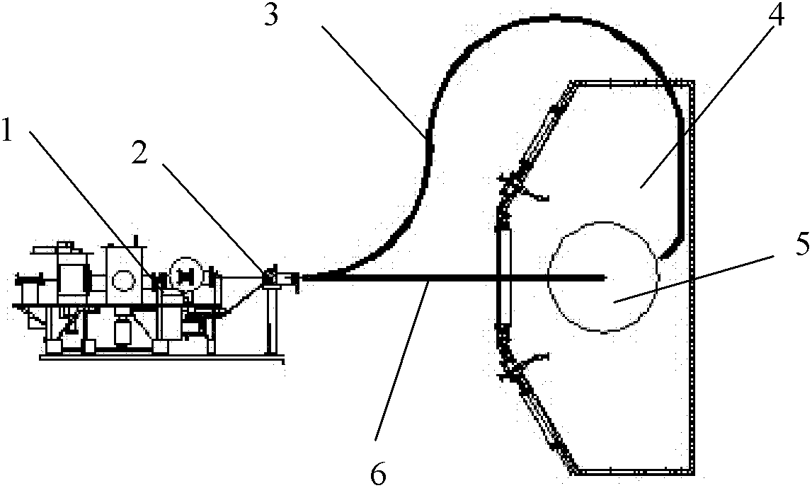
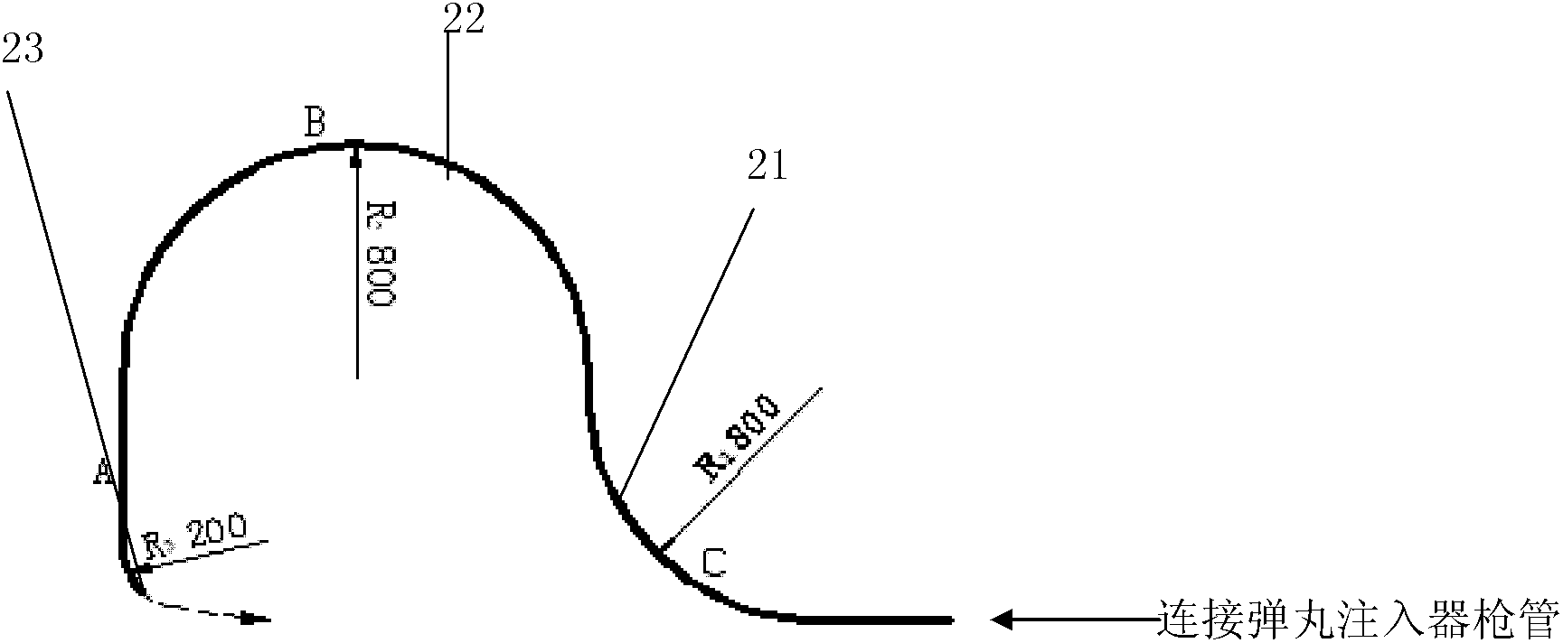
[0015] The overall structure of projectile injection on the strong field side and the weak field side is as follows: figure 1 As shown, the projectile injection pipeline design on the strong field side includes: three sections of curved conduits with different curvatures, converters, projectile diagnostic instruments (velocity measurement, imaging system), etc.

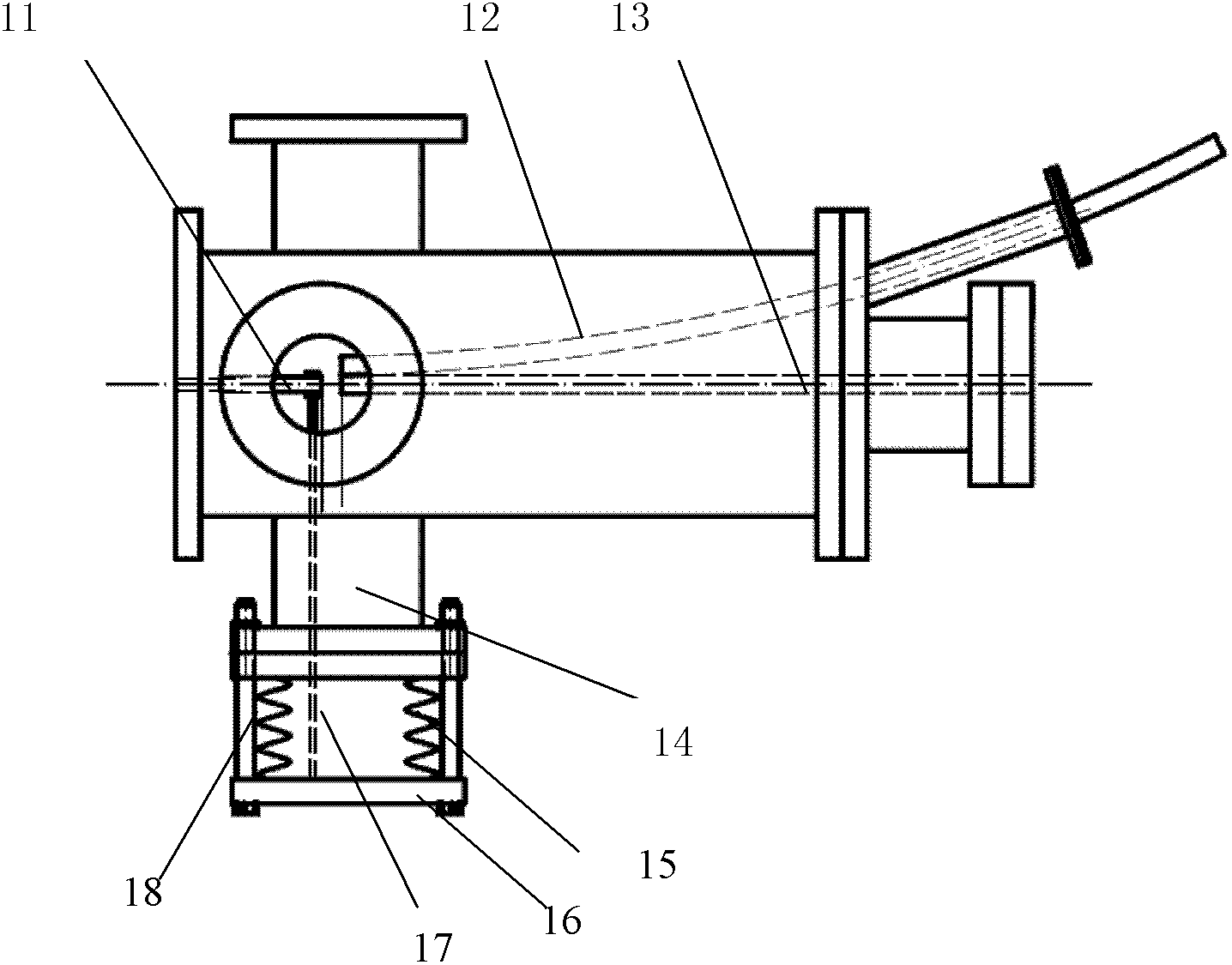
[0016] The function of the three-section curved conduit is to introduce the projectile from the outlet of the projectile injector barrel into the discharge vacuum chamber to realize the strong field injection of the projectile and ensure the integrity of the projectile in the curved conduit; the main function of the converter is to switch between strong and weak field injection The pipeline enables the flexible change of the projectile injection method; the projectile diagnostic instrument i...


PUM


Abstract

The invention belongs to the field of charging in fusion, particularly discloses a pipeline for injecting pellets from a strong field side and aims to provide a curved pipeline by which the pellets can be injected from the strong field side, so that a novel method for injecting the pellets is provided, the pellet charging efficiency is improved, and a plurality of physical experiments can be performed. The pipeline for injecting the pellets form the strong field side is connected to a strong field side of a discharging vacuum chamber (4) and comprises three sections of curved pipes, wherein the first section is a pipe C of which an inlet is connected with a gun barrel of a pellet injector to ensure that a flight path of each pellet which flies to a feeble field side of the discharging vacuum chamber (4) is changed; the second section is a pipe B by which the fly path of each pellet spans the discharging vacuum chamber (4) from one end of the feeble field to the strong field side; and the third section is a pipe A of which an outlet points to discharge plasma (5) in the discharging vacuum chamber (4) for finishing the charging process. The pipeline for injecting the pellets from the strong field side has the advantages that the pellet charging efficiency can be effectively improved, and a plurality of physical experiments can be performed.

Description

technical field [0001] The invention belongs to the field of fusion feeding, and in particular relates to the feeding and injection form of projectiles. Background technique [0002] In many foreign devices, projectile injection is usually carried out from the weak field side, because it is easier to realize in engineering. Projectile injection on the weak field side uses a linear pipeline to transport projectiles, and the speed of the projectile can be as high as 1km / s, and can maintain good projectile integrity. Accelerated projectiles such as the beam heating rocket effect can obtain a projectile velocity as high as 5km / s, but this level of projectile velocity is not enough for large-scale fusion reactor core feeding. It is difficult to solve the problem of core feeding only by increasing the initial velocity of projectile injection. Difficult, so it is necessary to find a new injection method or feeding technology, and the strong field side injection can inject projecti...

Claims


Application Information

Patent Timeline
Patent Type & Authority Patents(China)
IPC IPC(8): G21B1/15
CPCY02E30/16Y02E30/10
Inventor 徐红兵刘德权朱根良王明建
Owner SOUTHWESTERN INST OF PHYSICS
Learn More