Integrated ceiling

A technology of integrating suspended ceilings and suspended ceilings, applied in the direction of ceilings, building components, buildings, etc., can solve the problems of integrated suspended ceilings for buildings that cannot be expanded, and achieve the effects of rich design forms, strong practicability and wide application fields.

Active Publication Date: 2015-04-22
叶爱民
View PDF7 Cites 0 Cited by
  • Summary
  • Abstract
  • Description
  • Claims
  • Application Information

AI Technical Summary

Problems solved by technology

[0002] At present, the so-called integrated ceiling is actually the integrated ceiling of kitchen and bathroom. It uses metal materials, and its structure adopts general-purpose triangular keel and gusset plate. The main functional modules of the current integrated ceiling are lamp heating, lighting and exhaust fan electrical appliances. Its functional, structural, and material limitations make this type of ceiling only used in the field of kitchen and bathroom ceilings, and cannot be expanded to broader architectural integrated ceilings.

Method used


Image

  • Integrated ceiling
  • Integrated ceiling
  • Integrated ceiling

Examples


Embodiment 1

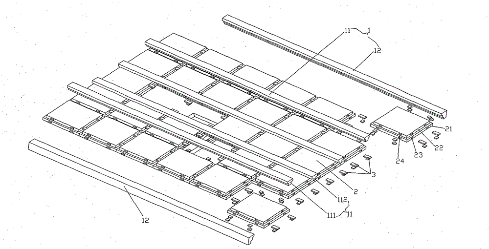
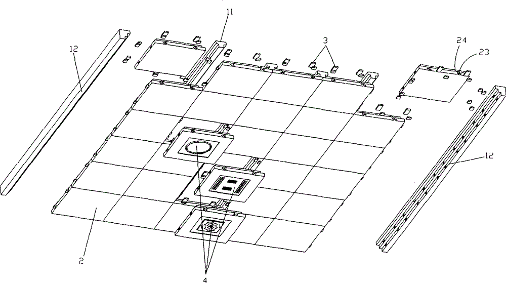
[0027] Such as Figure 1 to Figure 7 Shown: integrated ceiling, including keel 1, plug board 2 detachably installed on joist 1, plug pin 3 connecting plug board 2 through mortise and tenon structure, and electrical appliances installed on plug board 2 through mortise and tenon structure Host 4.

[0028] The keel 1 includes several T-shaped central keels 11 , crosspiece keels (not marked in the figure), and 2-4 L-shaped edge keels 12 . Both the keel 1 and the inserting plate 2 are made of wood or other composite materials. In a specific embodiment, the central keel 11 is T-shaped, and the entire keel is in the shape of a cuboid. The central keel 11 includes a keel beam and a keel shoulder. There are equidistant mortises on both sides of the keel beam, and the keel shoulder is connected to the main keel. The central keel 11 is distributed in the middle of the ceiling bracket in plural numbers, and the central keel 11 is connected with the plug board 2 , the plug board electric...

Embodiment 2

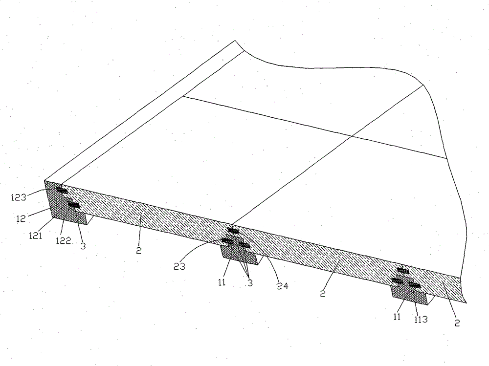
[0036] The difference between this embodiment and Embodiment 1 is that the height of the fifth socket 24 on the two mating boards 2 relative to the lower surface of the boards 2 is different, so that the two mating boards 2 are dislocated up and down. set up. In this way, the concavo-convex setting of the board 2 can be realized conveniently.

[0037]In a specific embodiment, the connection between the keel and the plugboard 2, and between the plugboard 2 and the plugboard electrical module adopts a metal connector, or a metal buckle, and the installation method of the metal connector is different from the mortise and tenon structure, or Use all of them, or use them together with tenon and tenon joints. The metal connectors are cuboid, or square, or round, or irregular sheets in the shape of buckles or anklets. There are multiple screw holes on the metal connectors. Screws are fixed on the inner side of the keel beam of the edge keel 12 and both sides of the keel beam of the ...


PUM


Abstract

The invention discloses an integrated ceiling which comprises a plurality of keels and plural spiles, wherein the spiles are arranged on the keels. The integrated ceiling is characterized in that the spiles are arranged on the keels through mortise and tenon joint structures. Through the integrated ceiling, a plurality of mortise and tenon joint mounting methods are structurally adopted, and the spiles, the keels and an electric appliance main engine are integrated, so that the mounting and the dismounting between the spiles and the keels as well as between the spiles are convenient, the use security is high, the construction time is short and the standardization degree is high.

Description

technical field [0001] The invention relates to the field of ceiling installation, in particular to an integrated suspended ceiling. Background technique [0002] At present, the so-called integrated ceiling is actually the integrated ceiling of kitchen and bathroom. It uses metal materials, and its structure adopts general-purpose triangular keel and gusset plate. The main functional modules of the current integrated ceiling are lamp heating, lighting and exhaust fan electrical appliances. Its functional, structural, and material limitations make this type of ceiling only used in the field of kitchen and bathroom ceilings, and cannot be expanded to broader architectural integrated ceilings. Contents of the invention [0003] The purpose of the present invention is to overcome the limitations of the existing integrated ceiling and provide an integrated ceiling that can be widely used in indoor living rooms, bedrooms, and other hotels, hotel halls, meeting rooms, reception ...

Claims


Application Information

Patent Timeline
Patent Type & Authority Patents(China)
IPC IPC(8): E04B9/00E04B9/02E04B9/06E04B9/28
Inventor 叶爱民
Owner 叶爱民
Why Eureka
Try Eureka