
Lifting device of isolating switch

A lifting device and isolating switch technology, applied in the direction of hoisting device, clockwork mechanism, etc., can solve the problems of labor intensity, high risk factor, narrow work place, limited power outage range, etc.

Inactive Publication Date: 2013-01-30
XINYANG POWER SUPPLY OF HENAN ELECTRIC POWER CORP
View PDF8 Cites 2 Cited by
  • Summary
  • Abstract
  • Description
  • Claims
  • Application Information

AI Technical Summary

Problems solved by technology

Due to the dense layout of isolating switches, pressure transformers, and rheology in the 220kV substation, the scope of power outages is limited, and the work site is small, mechanical cranes and large lifting tools cannot enter the work site; in the past, equipment was installed The whole is installed in parts, labor intensity and risk factor are very high

Method used


Image

  • Lifting device of isolating switch

Examples


Embodiment Construction

[0009] The technical solutions of the present invention will be described in further detail below through specific implementation methods.

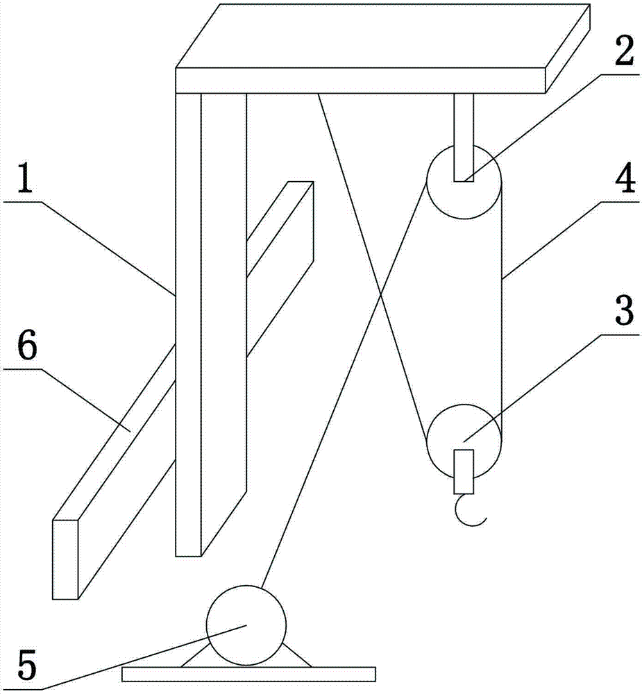
[0010] Such as figure 1 As shown, a disconnector lifting device includes a fixed plate 6, an L-shaped boom 1 and a lifting device, the fixed plate 6 is fixed on the vertical rod of the L-shaped boom, and the lifting device includes a hoist 5 , sling 4, the fixed pulley 2 that is fixed on the cross bar of described L shape suspender and the movable pulley 3 that hook is installed, one end of described sling 4 is connected with the rotating shaft of described winch 5, and described sling 4 The other end of the sling 4 passes through the fixed pulley 2 and the movable pulley 3 with a hook in turn, and the other end of the sling 4 is fixed on the cross bar of the L-shaped suspender.

[0011] Based on the above, when in use, the L-shaped suspension rod 1 is fixed on the installation column of the isolation switch at the work site through the ...


PUM


Abstract

The invention provides a lifting device of an isolating switch. The lifting device comprises a fixing plate, an L-shaped lifting rod and a lifting apparatus, wherein the fixing plate is fixed on a vertical rod of the L-shaped lifting rod. The lifting apparatus comprises a winch, a sling, a fixed pulley fixed on a cross rod of the L-shaped lifting rod and a moving pulley provided with a hook. One end of the sling is connected with a rotating shaft of the winch, and the other end of the sling sequentially penetrates through the fixed pulley and the moving pulley provided with the hook and is fixed on the cross rod of the L-shaped lifting rod. The lifting device of the isolating switch has the advantages of being scientific in design, strong in practicality, convenient to use and applicable to various working environments.

Description

technical field [0001] The invention relates to a disconnector installation device, in particular to a disconnector lifting device. Background technique [0002] With the improvement of people's living standards, the requirements for the power industry continue to increase. It is hoped that there will be power services with qualified voltage quality and uninterrupted power supply. RESPONSIBILITIES OF STAFF. Due to the dense layout of isolating switches, pressure transformers, and rheology in the 220kV substation, the scope of power outages is limited, and the work site is small, mechanical cranes and large lifting tools cannot enter the work site; in the past, equipment was installed The whole is installed in parts, and the labor intensity and risk factor are very large. [0003] In order to solve the above existing problems, people have been seeking an ideal technical solution. Contents of the invention [0004] The purpose of the present invention is to address the de...

Claims


Application Information

Patent Timeline
Patent Type & Authority Applications(China)
IPC IPC(8): B66D1/60
Inventor 李黔顾先伟蒋川
Owner XINYANG POWER SUPPLY OF HENAN ELECTRIC POWER CORP
Learn More