Spectrum Control Method for Pulse Modulation Waveform of All-Solid-State Transmitter

A technology of pulse modulation and control method, applied in pulse shaping, radio wave measurement system, instrument, etc., can solve problems such as secondary radar interference, and achieve the effect of reducing out-of-band spectrum distribution

Active Publication Date: 2015-08-19
NANJING NRIET IND CORP
View PDF4 Cites 0 Cited by
  • Summary
  • Abstract
  • Description
  • Claims
  • Application Information

AI Technical Summary

Problems solved by technology

[0008] The purpose of the present invention is to solve the problem that the existing secondary radar is easily interfered by other equipment, airport electromagnetic and other wireless signals, and to invent a method that can ensure that the transmitter of the secondary radar can generate pulse modulation waveforms and launch signals that meet the requirements of air traffic control. Power output, but also to make the spectrum characteristics of the secondary radar emission waveform meet the requirements of Annex 10 "Aviation Telecommunications" of the Convention on International Civil Aviation issued by the International Civil Aviation Organization (ICAO), and the "Secondary Surveillance of Air Traffic Control" issued by the Civil Aviation Administration of China. Spectrum control method for all solid-state transmitter pulse modulation waveforms in accordance with the requirements for the spectrum characteristics of secondary radar transmission waveforms in Radar Equipment Technical Specifications (MH 4010-2006)

Method used


Image

  • Spectrum Control Method for Pulse Modulation Waveform of All-Solid-State Transmitter
  • Spectrum Control Method for Pulse Modulation Waveform of All-Solid-State Transmitter
  • Spectrum Control Method for Pulse Modulation Waveform of All-Solid-State Transmitter

Examples


Embodiment Construction

[0024] The following structure accompanying drawing embodiment will further illustrate the present invention.

[0025] Such as Figure 1-6 shown.

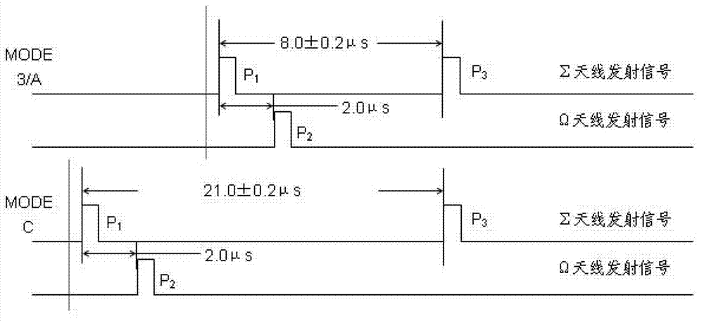
[0026] A spectrum control method for the pulse modulation waveform of a secondary radar all-solid-state transmitter. The conventional secondary radar has two working modes: 3 / A mode and C mode. 3 / A mode asks for the A code of the aircraft, and C mode asks for the barometric altitude code of the aircraft. When the secondary radar works in the 3 / A mode, the interval between the secondary radar interrogation pulses P1 and P3 is 8 μS, and the airborne transponder sends the corresponding 3 / A mode response code after receiving the interrogation signal; the secondary radar When working in the C mode, the interval between the secondary radar interrogation pulses P1 and P3 is 21 μS, and the airborne transponder sends out the corresponding C mode response code after receiving the secondary radar interrogation signal. The secondary radar s...


PUM


Abstract

The invention discloses a spectrum control method for a pulse modulation waveform of a full-solid-state emitter. The method is characterized by comprising the following steps that: 1, a PIN switch modulator is added at the input end of the emitter, the excitation input signal of the emitter shaped in advance, and a rising edge and a falling edge of an original steep excitation pulse signal are enlarged; 2, the modulation pulse width of the PIN switch modulator is equal to the emission output pulse width, the pulse width of the excitation signal is greater than the modulation pulse width of a PIN switch, and a set time relation is kept between the modulation pulse of the PIN switch modulation and the excitation signal; and 3, a leakage stage modulation technology is adopted and strict pulse time sequence control is performed at the first stage of the radio frequency amplification chain of the emitter. By the spectrum control method, the out-of-band spectrum distribution of an emission signal is greatly reduced, so that a spectrum of an emission waveform can meet an index requirement.

Description

technical field [0001] The invention relates to a secondary radar transmission technology, in particular to a method suitable for controlling the output spectrum of an all-solid-state transmitter whose waveform is a pulse modulation mode, specifically a method for controlling the pulse-modulated waveform of an all-solid-state transmitter spectrum control method. Background technique [0002] Radio frequency spectrum is a very precious and limited natural resource. It has both the common characteristics of general resources and the individuality that general resources do not have. The first is its limitation. Although it can perform frequency multiplexing according to its three-dimensional elements of space, time and frequency, the three are interrelated. The use is limited under certain conditions; the second is its non-depletion, which is different from land, water, minerals and other renewable or non-renewable resources. It is a waste not to use it, and it is also a waste...

Claims


Application Information

Patent Timeline
Patent Type & Authority Patents(China)
IPC IPC(8): H03K5/02G01S7/282
Inventor 张虹任治国
Owner NANJING NRIET IND CORP
Why Eureka
Try Eureka