Step-up dc-dc converter

A DC-DC and converter technology, applied in the field of step-up DC-DC converters, to achieve the effect of reducing fluctuating voltage, preventing sound and malfunction

Inactive Publication Date: 2013-01-23
MITSUMI ELECTRIC CO LTD
View PDF1 Cites 5 Cited by
  • Summary
  • Abstract
  • Description
  • Claims
  • Application Information

AI Technical Summary

Problems solved by technology

Therefore, Imax cannot be unilaterally reduced regardless of Iout(MAX)
In addition, although according to formula (1), it can be known that increasing the capacitance value Cout of the output capacitor C0 or reducing the value of the inductor L1 can reduce the fluctuation voltage, but the value of the output capacitor C0 or the value of the inductor L1 is sometimes not enough to obtain the DC- The necessary characteristics of the DC converter cannot be freely changed

Method used


Image

  • Step-up dc-dc converter
  • Step-up dc-dc converter
  • Step-up dc-dc converter

Examples


Embodiment Construction

[0053] Preferred embodiments of the present invention will be described below with reference to the drawings.

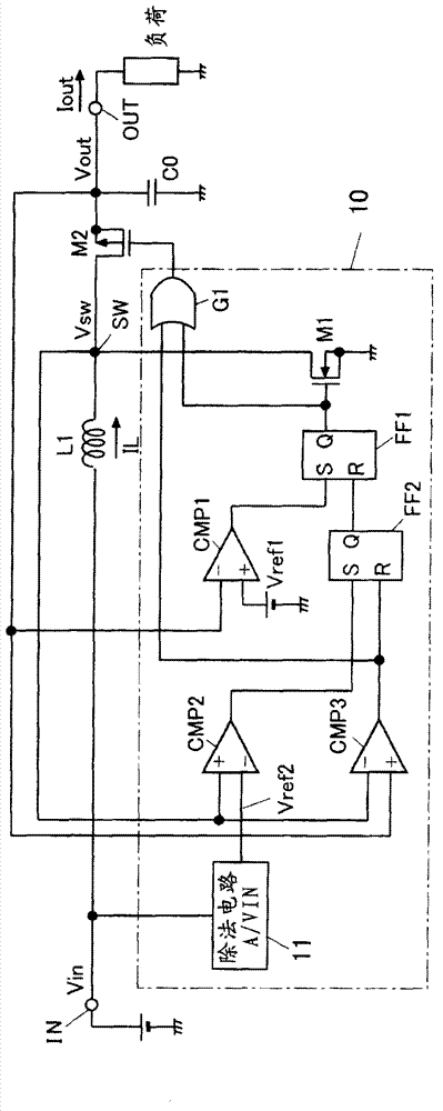
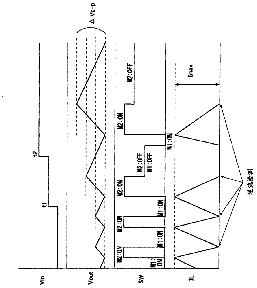
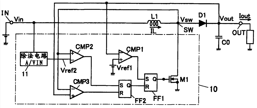
[0054] figure 1 An embodiment of a step-up DC-DC converter with output controlled by a PFM (Pulse Frequency Modulation) method to which the present invention is applied is shown.

[0055] The DC-DC converter of this embodiment has: a coil L1 as an inductor, one terminal of which is connected to a voltage input terminal IN to which a DC input voltage Vin is applied; The switching element M1 for driving; and the switching element M2 for rectification connected between the connection node (terminal SW) of the coil L1 and the switching element M1 and the output terminal OUT. The switching element M1 for driving can be composed of an N-channel MOSFET (Insulated Gate Field Effect Transistor), and the switching element M2 for rectification can be composed of a P-channel MOSFET.

[0056] In addition, the DC-DC converter of the present embodiment includes a switch control ...


PUM


Abstract

A step-up DC-DC converter has a switching element for feeding current to an inductor; a rectifier connected to the output side of the inductor; and a control circuit performing on / off control of the switching element, based on an output voltage and a voltage corresponded to the inductor current. The control circuit further has a first voltage comparator circuit detecting fall of the output voltage down to the first reference voltage; a second voltage comparator circuit detecting that the inductor current reached a predetermined current value; and a voltage generation circuit generating a voltage inversely proportional to an input voltage and feeds the voltage, as a second reference voltage, to the second voltage comparator circuit. The switching element turns on, when the output voltage fell down to the first reference voltage, whereas the switching element turns off, when voltage proportional to the inductor current rose up to the second reference voltage.

Description

technical field [0001] The present invention relates to a step-up type power supply device of switch / regulator type for converting direct current voltage, in particular to a step-up type DC-DC converter for controlling output by PFM (Pulse Frequency Modulation) method. Background technique [0002] As a circuit that converts a DC input voltage and outputs a DC voltage of a different potential, there is a switch / regulator type DC-DC converter. In the above-mentioned DC-DC converter, there is a DC-DC converter having a driving switching element, a rectifying element, and a control circuit. The above-mentioned driving switching element is used to apply DC power from a battery or the like to the inductor (coil). The DC voltage supplied makes the current flow and accumulates energy in the coil. The above-mentioned rectifying element is used to rectify the current of the coil when the driving switching element is turned off to release energy. The above-mentioned control circuit is...

Claims


Application Information

Patent Timeline
Patent Type & Authority Applications(China)
IPC IPC(8): H02M3/156
CPCH02M3/157H02M2001/0022H02M3/156H02M1/0022
Inventor 田渊仁之广岛隆
Owner MITSUMI ELECTRIC CO LTD
Why Eureka
Try Eureka