Oblique scan display method in direct writing photoetching system

A lithography system and oblique scanning technology, which is applied in the field of oblique scanning display in direct-write lithography systems, can solve the problems of reducing image resolution and minimum line width, and achieve the effect of optimizing working mode and improving efficiency

Active Publication Date: 2014-05-14
TIANJIN ADVANTOOLS
View PDF5 Cites 0 Cited by
  • Summary
  • Abstract
  • Description
  • Claims
  • Application Information

AI Technical Summary

Problems solved by technology

The exposure speed is related to the actual projected pixel size and the update speed of the micromirror DMD image. When the micromirror DMD image update speed is constant, the actual projected pixel size is directly related to the exposure speed, but the actual projected pixel size is related to the resolution of the image. Ratio related, increasing the grid of pixels will reduce the resolution and minimum line width of the image

Method used


Image

  • Oblique scan display method in direct writing photoetching system
  • Oblique scan display method in direct writing photoetching system
  • Oblique scan display method in direct writing photoetching system

Examples


Embodiment Construction

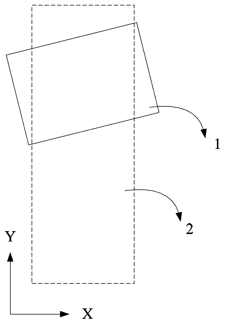
[0024] The invention is a method for obliquely scanning and displaying images in a direct writing photolithography system.

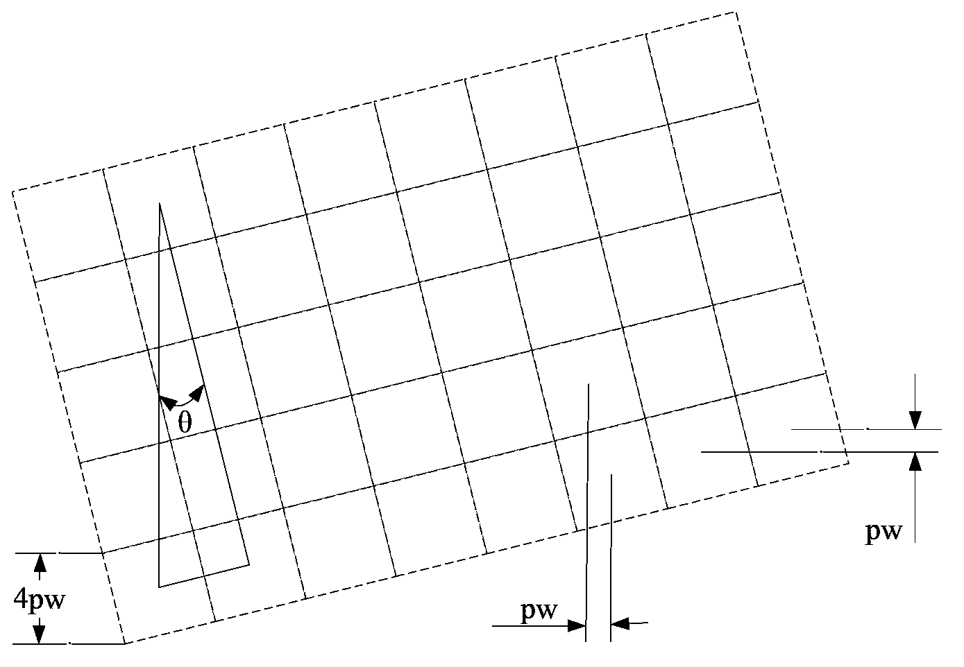
[0025] refer to figure 1 , figure 2 , the micromirror DMD1 of the present invention is fixedly installed with an inclination, the micromirror DMD1 rotates 14.0362 ° counterclockwise when the tilt factor N=4, and the micromirror DMD1 rotates 7.125 ° counterclockwise when the tilt factor N=8, selects the tilt factor N= in the present embodiment 4; The exposure surface is sucked on the platform 2 and can move back and forth in the Y direction. exist figure 2 The figure shows the 5×8 partial diagram of the micromirror DMD1 installed obliquely. It can be seen from the figure that when the tilt factor N=4, the rotation angle θ=14.0362°. Assuming that the length and width of a projected pixel are respectively pl, it can be Calculate pw=pl×0.24254, the centers of two columns of pixels connected by the tilted micromirror DMD1 are 4pw in X direction and 1...


PUM


Abstract

The invention discloses an oblique scan display method in a direct writing photoetching system. N2 rows of data are combined and stored in a memory in sequence according to an obliquity factor N and on the basis of left-justified N rows and N lines of pixel data, and an FPGA (field programmable gate array) selects the data in the corresponding rows in sequence according to the platform motion to a DMD (digital micro-mirror display) to display. According to the invention, the data are stored in a DDR2 (double data rate 2), the DMD is controlled by the FPGA, and the oblique scan display is a method for updating an image according to the obliquity factor and a platform scanning manner, so that the operating mode of the FPGA can be conveniently designed and optimized, and the data reading efficiency of the DDR2 can be improved.

Description

technical field [0001] The invention relates to the technical field of lithography in the semiconductor industry and the printed circuit board industry, in particular to an oblique scanning display method in a direct-writing lithography system. Background technique [0002] The digital micromirror is composed of many tiny aluminum-coated lenses, which can rotate around the yoke with a rotation angle of ±12°, and use the lenses to reflect the incoming light to different places at different rotation angles. The direct writing exposure system uses a collimated laser to inject into the digital micromirror DMD, and the DMD rotates to different positions according to the image data, and reflects the injected laser on the objective lens, and the image is scaled by the objective lens and then projected onto the exposure surface on the mobile platform . The small lenses on the micromirror (DMD) are arranged in a row and column format, and the displayed image needs to be rasterized d...

Claims


Application Information

Patent Timeline
Patent Type & Authority Patents(China)
IPC IPC(8): G03F7/20
Inventor 陈勇陈修涛张爱民
Owner TIANJIN ADVANTOOLS
Why Eureka
Try Eureka