Eureka AIR delivers breakthrough ideas for toughest innovation challenges, trusted by R&D personnel around the world.

A flow monitoring device and flow monitoring method based on visual detection

A flow monitoring and visual inspection technology, applied in the direction of volume/mass flow generated by mechanical effects, which can solve the problems of inability to realize remote transmission of flow data, inability to realize visual monitoring and reading, etc.

Inactive Publication Date: 2014-10-22
BEIJING INFORMATION SCI & TECH UNIV
View PDF3 Cites 0 Cited by
  • Summary
  • Abstract
  • Description
  • Claims
  • Application Information

AI Technical Summary

Problems solved by technology

The advantage of glass tapered tube rotameter is that it can realize on-site visual reading, but it cannot realize the remote transmission of flow data, that is, flow monitoring and out-of-tolerance alarm, etc.
The metal conical tube rotameter measures the position of the float through the sensor, which can realize the electric remote transmission of the measurement data, so as to realize the monitoring and over-tolerance alarm, but cannot realize the on-site visual monitoring and reading

Method used


Image

  • A flow monitoring device and flow monitoring method based on visual detection
  • A flow monitoring device and flow monitoring method based on visual detection
  • A flow monitoring device and flow monitoring method based on visual detection

Examples


Embodiment Construction

[0020] Reference will now be made in detail to embodiments of the invention, examples of which are illustrated in the accompanying drawings, wherein like reference numerals refer to like parts throughout. The embodiments are described below in order to explain the present invention by referring to the figures.

[0021] 1. Specific implementation of the flow monitoring device based on visual detection

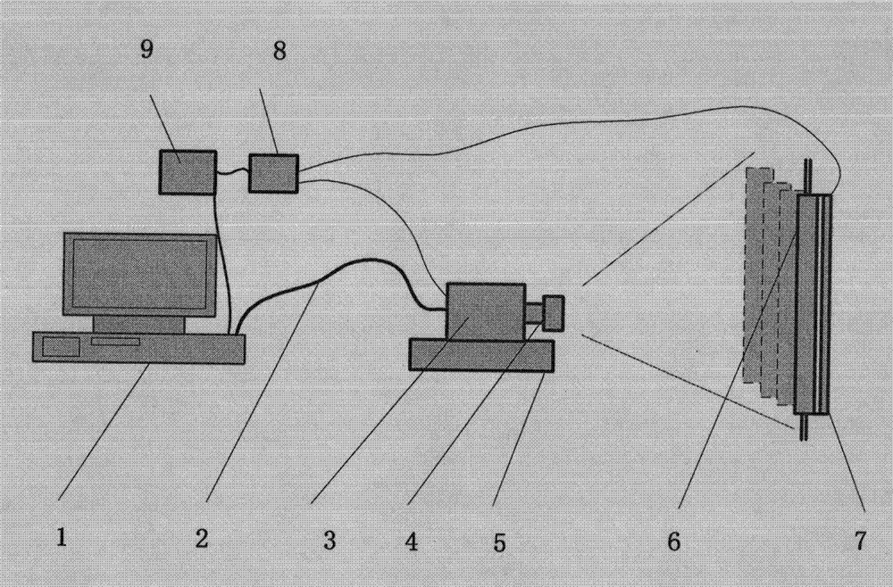
[0022] refer to figure 1 , is a schematic diagram of a flow monitoring device based on visual detection according to an embodiment of the present invention. In the figure: 1 is the computer, 2 is the video cable, 3 is the CCD camera, 4 is the optical lens, 5 is the adjusting fixture of the visual inspection system, 6 is the glass float flowmeter, 7 is the lighting source, 8 is the switching power supply, 9 It is 220V power supply. In the figure, a visual inspection system is used to collect images of four glass rotameters.

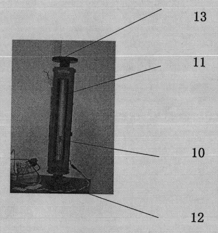
[0023] refer to figure 2 It is the physical pict...


PUM


Abstract

The invention discloses a flow monitoring device and a flow monitoring method based on visual inspection. The device mainly comprises a glass floater flow meter, an illumination light source, an optical lens, a CCD (charge coupled device) camera and a computer. The glass floater flow meter is connected into a flow pipeline to be measured; the illumination light source is a red LED (light emitting diode) flat light source for back lighting of the glass floater flow meter; the CCD camera and the optical lens form a visual inspection system to shoot images of the glass floater flow meter; and computer software is used for collecting and processing the images of the CCD camera. The flow monitoring method comprises the following steps: flow monitoring software displays the images of the CCD camera in real time and processes the images so as to acquire the positions of the floaters of the flow meters in the images, the flow indications of the glass floater flow meter are calculated according to the linear interpolation of the corresponding relationship between pre-marked positions of scale marks of the flow meters and flow indications, whether the flow indications are within a preset range is judged, the flow indications are displayed and stored, and the total volume of the fluid is calculated.

Description

technical field [0001] The invention relates to a flow monitoring device and a flow monitoring method based on visual detection, which belong to the field of photoelectric measurement and are suitable for real-time monitoring of fluid flow in pipelines, storage and statistical analysis of flow data. Background technique [0002] A flow meter is defined as: An instrument that indicates the measured flow rate or the total amount of fluid over a selected time interval. Simply put, it is a kind of instrument used to measure the flow of fluid in the pipeline. The material flowing through it can be gas, liquid or solid. It can be divided into instantaneous flow and cumulative flow. The instantaneous flow is the amount of the effective section of the closed pipeline per unit time. The cumulative amount of the section. The cumulative flow can also be obtained by integrating the instantaneous flow with respect to time, so the instantaneous flowmeter and the cumulative flowmeter can...

Claims


Application Information

Patent Timeline
Patent Type & Authority Patents(China)
IPC IPC(8): G01F1/52
Inventor 刘力双吕勇郎晓萍燕必希娄小平
Owner BEIJING INFORMATION SCI & TECH UNIV
Why Eureka
Eureka Blog
Learn More