Hydraulic rock drill and impactor and flow equalizing valve for the rock drill

A technology of flow equalizing valve and impactor, applied in the field of impactor, equalizing valve and hydraulic rock drill, can solve the problems of inefficiency, lack of actual efficiency, reduced energy utilization rate, etc., to eliminate rotary motion, eliminate inefficiency loss, The effect of improving energy utilization

Inactive Publication Date: 2016-05-25
深圳市普隆重工有限公司
View PDF5 Cites 0 Cited by
  • Summary
  • Abstract
  • Description
  • Claims
  • Application Information

AI Technical Summary

Problems solved by technology

[0003] The problems of existing impactors are: first, due to the structural nature of the oil passage, the outlet of the eccentric groove can only be set on the side that deviates from the centerline of the impact piston; second, because the working oil pressure required by the impactor is generally All are P≥10MPa, the ideal value is P≥17-20MPa, and the flow rate Q≥50L / min, such a pressure oil enters the oil chamber of the piston from the side off the center line of the piston, according to Bernoulli Law, when the pressure energy and velocity kinetic energy of the fluid (not considering the position potential energy) are converted into the impact force of the impacting piston, part of it is converted into the torque energy that makes the piston rotate, and this part of the torque energy has no actual efficiency , thus causing a waste of energy
Due to the law of energy conservation, the rotary motion of the impact piston 101 will consume part of the energy, resulting in energy loss, and this part of the lost capacity is inefficient, so the energy utilization rate is reduced
[0006] Although the position of the eccentric groove has been designed as symmetrically as possible in the structural design, the above problems cannot be overcome after all.

Method used


Image

  • Hydraulic rock drill and impactor and flow equalizing valve for the rock drill
  • Hydraulic rock drill and impactor and flow equalizing valve for the rock drill
  • Hydraulic rock drill and impactor and flow equalizing valve for the rock drill

Examples


Embodiment 1

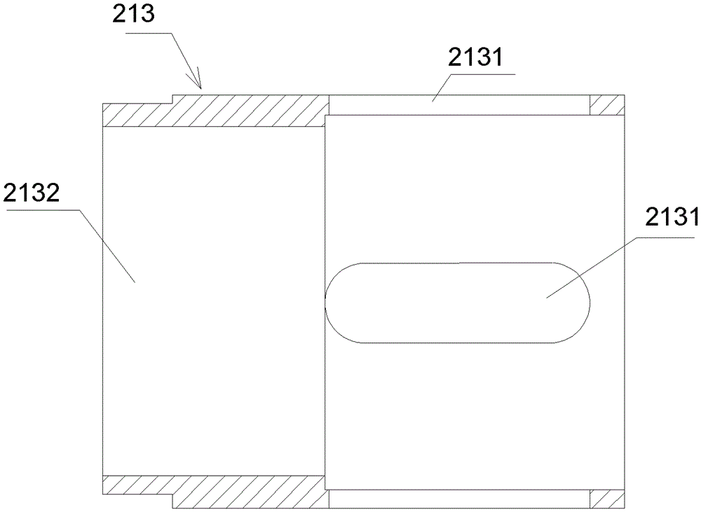
[0025] Please refer to figure 2 , the present invention is a flow equalizing valve 213 for hydraulic rock drill impactor, including a valve body for installation in the impact oil cylinder; There is a through flow equalizing hole 2131, which communicates with the valve cavity 2132, and the center line of the flow equalizing hole 2131 is perpendicular to the center line of the valve cavity 2132, so as to ensure that the pressure flow line in the oil inlet direction is consistent with that of the impacting piston. Centerlines are perpendicular to each other.

[0026] In order to more effectively counteract the tangential force of the fluid on the impact piston, the number of equalizing valves 213 is preferably an even number, and are evenly and symmetrically distributed on the valve body around the centerline of the valve cavity 2132 . In this example, the flow equalizing valve 213 is designed to be larger in volume, and the equalizing hole 2131 is in the shape of a long groov...


PUM


Abstract

The invention provides a flow equalizing valve used for an impact of a hydraulic rock drill. The flow equalizing valve comprises a valve body arranged in an impact oil cylinder, wherein the valve body is in a revolving form, and is provided with a valve chamber along the axial direction in a penetrating mode; the valve body is provided with a through flow equalizing hole, the flow equalizing hole is communicated with the valve chamber, and the central line of the flow equalizing hole perpendicularly intersects with the central line of the valve chamber; and front piston chamber and a back piston chamber are internally provided with the flow equalizing valves. Through the flow guiding function of the flow equalizing valves, the pressure flow line in the oil taking direction of high pressure oil perpendicularly intersects with the central line of an impact piston, so that the tangential forces of the high pressure oil on the impact piston are mutually cancelled out, and the resultant moment of tangential force is zero, and the flow equalizing valve can eliminate the rotary motion of the impact piston caused by the action of the tangential force in the prior art, avoids the inefficiency loss of energy, and enhances the energy utilization.

Description

technical field [0001] The invention relates to the field of rock drilling machines, in particular to a hydraulic rock drilling machine, an impactor and a flow equalizing valve used for the rock drilling machine. Background technique [0002] Hydraulic rock drill impactor is the core component of hydraulic rock drill products. [0003] The problems of existing impactors are: first, due to the structural nature of the oil passage, the outlet of the eccentric groove can only be set on the side that deviates from the centerline of the impact piston; second, because the working oil pressure required by the impactor is generally All are P≥10MPa, the ideal value is P≥17-20MPa, and the flow rate Q≥50L / min, such a pressure oil enters the oil chamber of the piston from the side off the center line of the piston, according to Bernoulli Law, when the pressure energy and velocity kinetic energy of the fluid (not considering the position potential energy) are converted into the impact f...

Claims


Application Information

Patent Timeline
Patent Type & Authority Patents(China)
IPC IPC(8): E21B1/26F15B13/02
Inventor 王造时
Owner 深圳市普隆重工有限公司
Why Eureka
Try Eureka