Concealed hinges for furniture

A technology for concealed hinges and furniture, applied in the field of hinges, can solve the problems of wear between torsion springs and parts, strong contact pressure, affecting the life of torsion spring hinges, etc., to reduce rigid friction, reduce pressure, and open and close smoothly and reliably.

Active Publication Date: 2015-11-18
伍志勇
View PDF7 Cites 3 Cited by
  • Summary
  • Abstract
  • Description
  • Claims
  • Application Information

AI Technical Summary

Problems solved by technology

However, because the diameter of the torsion spring steel wire is very small, the contact portion between the support leg of the torsion spring and the part is very small, almost a point contact, so the pressure at the contact is strong, resulting in serious wear between the torsion spring and the part, affecting the torsion spring. even the life of the entire hinge

Method used


Image

  • Concealed hinges for furniture
  • Concealed hinges for furniture
  • Concealed hinges for furniture

Examples


no. 1 example

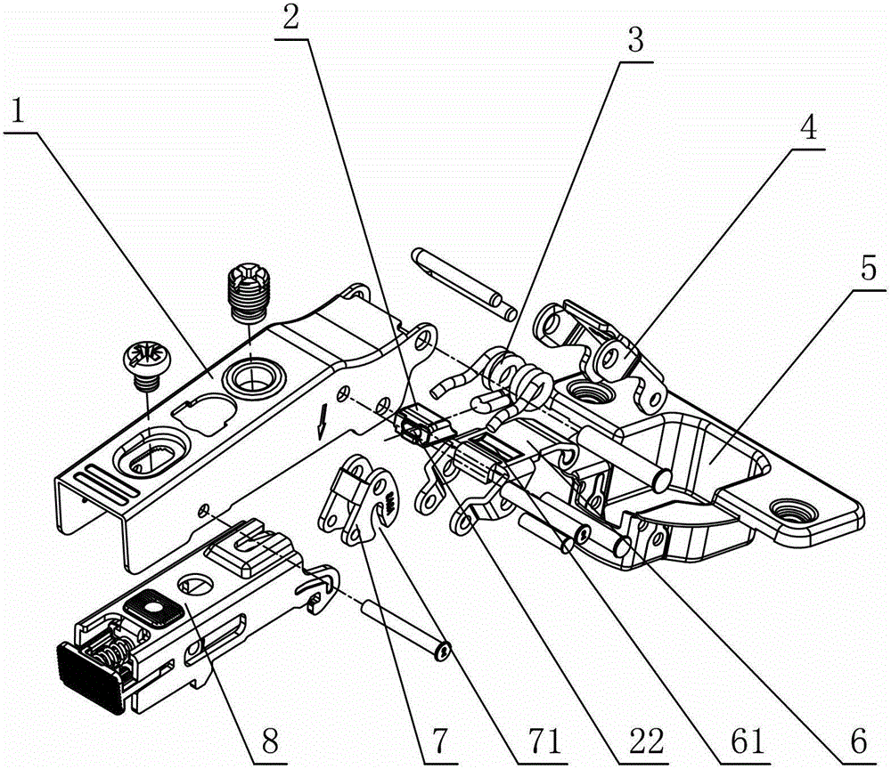
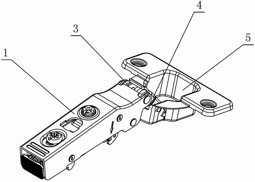
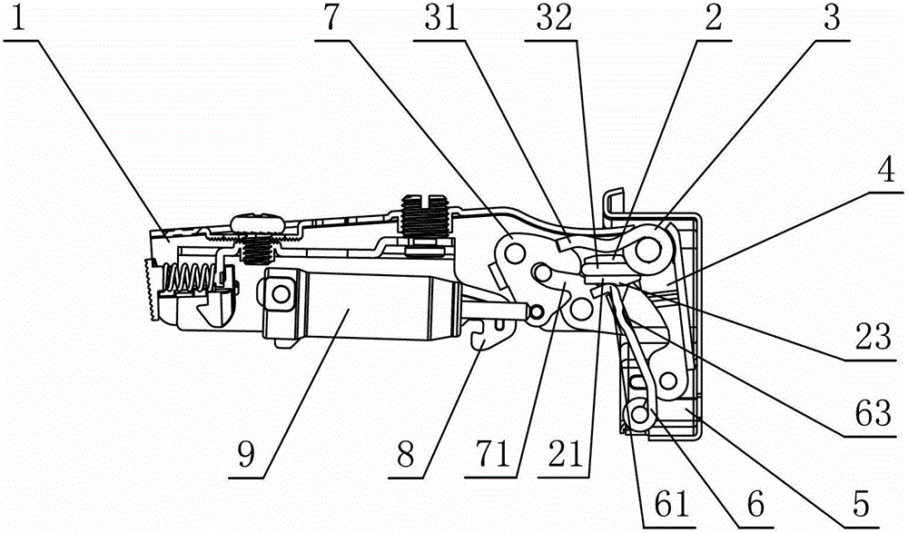
[0036] see figure 1 - Figure 6 , the concealed hinge used for this furniture, including the connecting arm 1 and the movable cup holder 5 connected by the swing arm assembly, the hinge is provided with a torsion spring 3 that at least generates an opening and closing force on the movable cup holder 5, and the torsion spring 3 has at least one supporting foot The positioning block 2 is provided with a sliding connection with the swing arm; the positioning block 2 is provided with a contact surface 21, and the contact surface 21 is slidingly connected with the swing arm in the opening and closing process of the hinge; Part of the limit is fixed on a supporting foot and / or swing arm of the torsion spring 3.

[0037] The components of the hinge are combined as follows: the swing arm assembly includes the outer swing arm 4 and the inner swing arm 6; the two ends of the outer and inner swing arms are respectively hinged with the connecting arm 1 and the movable cup holder 5; , th...

no. 2 example

[0042] see Figure 7 One end of the contact surface 21 of the positioning block 2 is provided with a groove 24, and the inner swing arm 6 is provided with a boss B64 corresponding to the groove 24 to cooperate with its concave and convex, so that the positioning block 2 is limited and fixed on the inner swing arm 6. Other unmentioned parts are the same as the first embodiment.

no. 3 example

[0044] see Figure 8 , the inner wall of the sleeve hole 22 of the positioning block 2 is provided with a protrusion 25 , and the positioning block 2 is limited and fixed on the middle support leg 32 of the torsion spring 3 through the protrusion 25 . Other unmentioned parts are the same as the first embodiment.


PUM


Abstract

The invention provides a blind hinge for furniture. The blind hinge comprises a connecting arm and a movable cup base which are connected through a swinging arm, wherein the hinge is internally provided with a torsion spring which is at least used for generating opening / closing acting force on the movable cup base. The blind hinge is characterized in that at least one supporting foot of the torsion spring is provided with a positioning block which is slidingly connected with the swinging arm; the positioning block is provided with a contact face and the contact face is slidingly connected with the swinging arm in an opening / closing process of the hinge; the positioning block is further provided with a limiting block; and a limiting part is fixedly arranged on one supporting foot and / or the swinging arm of the torsion spring in a limiting manner. According to the blind hinge disclosed by the invention, the positioning block is arranged on the supporting foot of the torsion spring so that the limiting block is fixedly arranged on one supporting foot and / or the swinging arm of the torsion spring in the limiting manner and is contacted with a hinge part; the mutual contact face of the positioning block and the hinge part is a curved surface, a plane or a combination of the curved surface and the plane so that the contact between the positioning block and the hinge part is in linear contact or face contact and the pressure of the contact part is greatly reduced; and the positioning block is a plastic anti-wearing plastic piece so that the rigid friction between the torsion spring and the hinge part is reduced, the abrasion is reduced, the service life of a product is prolonged and the aim of smoothly and reliably opening and closing the hinge is achieved.

Description

technical field [0001] The invention relates to a hinge, in particular to a concealed hinge for furniture. Background technique [0002] Chinese Patent Document No. CN1873178 disclosed a hinge device on December 6, 2006, which has: an elongated first body installed on the furniture body; a cover-shaped second body installed on the door; the second body The first and second chain links rotatably connected to the first body; and the torsion spring, one end of the torsion spring pushes the spring receiving plate of the first chain link, thereby, the second body faces the first The main body rotates and applies force, one end of the torsion spring is disposed between the side wall of the first main body and the side wall of the second link, the gap between the spring receiving plate and the side wall of the first main body, and the gap between the spring receiving plate and the side wall of the second link. The gaps between the side walls of the second link are all smaller than...

Claims


Application Information

Patent Timeline
Patent Type & Authority Patents(China)
IPC IPC(8): E05D3/06E05D5/02E05F1/12E05F1/14E05F3/20
Inventor 伍志勇
Owner 伍志勇
Why Eureka
Try Eureka