Hinge
A technology of hinges and connecting feet, which is applied in the field of hinges, can solve problems such as wear of parts, affecting the life of torsion spring hinges, and high pressure at the contact point, so as to achieve the effects of reducing pressure, less wear, and improving service life
- Summary
- Abstract
- Description
- Claims
- Application Information
AI Technical Summary
Problems solved by technology
Method used
Image

Examples
no. 1 example
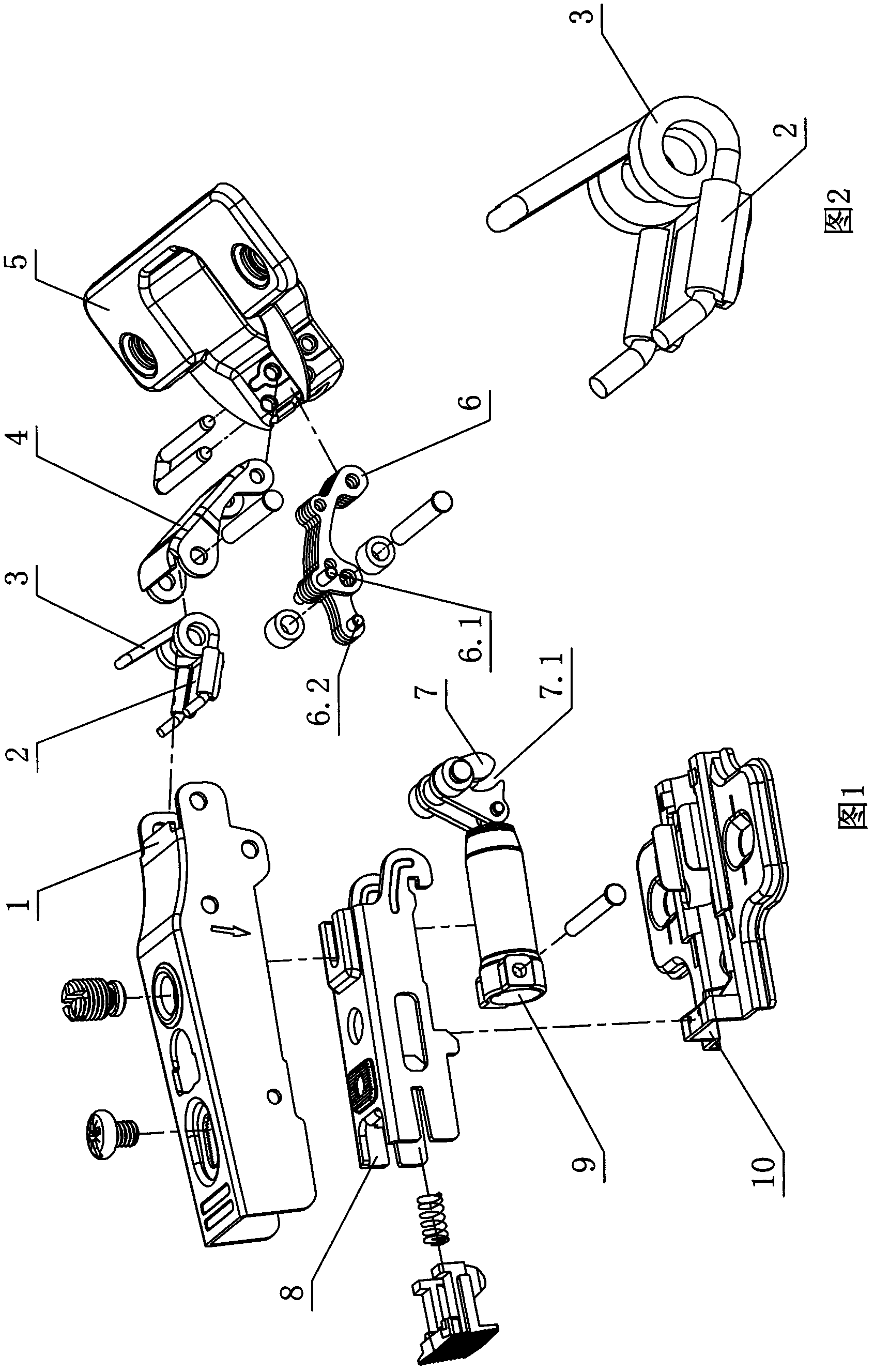
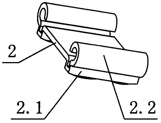
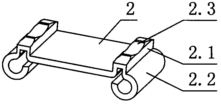
[0038] see Figure 1-Figure 5 , the hinge includes a torsion spring 3, the middle section of the torsion spring is provided with a first connecting foot 3.1, and the two ends of the torsion spring are respectively provided with a second connecting foot 3.2; the first and second connecting feet move relative to the hinge opening and closing process respectively The two parts are connected. The same connecting block 2 is fixedly arranged on the two second connecting feet, and the connecting block is provided with a contact surface 2.3, and is connected with a part of the hinge through the contact surface. The contact surface 2.3 of the connection block 2 is a curved surface.
[0039] The hinge includes the following parts: a fixed seat 10, a movable seat 5, a fixed arm 8 fixedly connected to the fixed seat, a connecting arm 1 arranged on the fixed arm, and an outer rocker 4 and an inner rocker respectively hinged with the connecting arm and the movable seat The arm 6 and the t...
no. 2 example
[0044] see Figure 8-Figure 13 , the connecting block 22 is in the shape of a plate, and its corresponding second connecting leg of the torsion spring 3 is provided with a fixing sleeve 22.1; the fixing sleeve is sleeved on the second connecting leg, and is clamped and fixed with the second connecting leg. The bottom surface of the connection block 22 is a contact surface, and the inner rocker arm 6' is provided with a contact portion 6.1' to connect with the contact surface. The bottom surface of the connection block 22 is a plane.
[0045] The above connection block can be designed as Figure 14 In the connection block 22' shown, the contact surface 22.1' of the connection block 22' is a curved surface. The above connection block can also be designed as Figure 15 The connecting block 32 shown is ring-shaped, sleeved on the two second connecting legs of the torsion spring, and the second connecting legs protrude from the rear end of the connecting block 32 and are provide...
no. 3 example
[0048] see Figure 16 , there are two torsion springs 3', and the two ends of the torsion springs are respectively provided with a first connecting foot 3.1' and a second connecting foot 3.2'; the first connecting feet of each torsion spring are connected to the connecting arm or the outer rocker arm; The second connecting pin of each torsion spring passes through a connecting block 12 ( Figure 16 Listed in is the connection block 12, in fact the connection blocks can also be connected together in other embodiments. The end of the second connecting leg 3.2' of the torsion spring 3' is provided with an anti-off bending 3.3'.
[0049] Other unmentioned parts are the same as the first or second embodiment.
PUM
 Abstract
Description
Claims
Application Information
 - R&D
- Intellectual Property
- Life Sciences
- Materials
- Tech Scout
- Unparalleled Data Quality
- Higher Quality Content
- 60% Fewer Hallucinations
Browse by: Latest US Patents, China's latest patents, Technical Efficacy Thesaurus, Application Domain, Technology Topic, Popular Technical Reports.
© 2025 PatSnap. All rights reserved.Legal|Privacy policy|Modern Slavery Act Transparency Statement|Sitemap|About US| Contact US: help@patsnap.com