
Hydraulic circuit capable of accurately controlling lifting height of movable arm of excavator

A precise control, hydraulic circuit technology, applied in mechanically driven excavators/dredgers, etc., can solve the problems of inaccurate lifting and positioning of excavators, reducing the operating efficiency of hydraulic excavators, and inability to accurately control the boom cylinders, etc. Achieve the effect of improving work efficiency, simple structure and sensitive control action

Inactive Publication Date: 2013-01-23
中外合资沃得重工(中国)有限公司
View PDF7 Cites 2 Cited by
  • Summary
  • Abstract
  • Description
  • Claims
  • Application Information

AI Technical Summary

Problems solved by technology

With the improvement of people's functional requirements for excavators, it is necessary to replace the extended boom for the excavator, or to complete the excavation within a limited space, but the lifting height of the existing excavator boom is mainly controlled manually by the operator visually. When reaching the predetermined height, the manual control makes the boom cylinder slow down the expansion and contraction speed, so that it slowly rises to the predetermined height. Due to the visual error, it is impossible to accurately control the retraction stroke of the boom cylinder, and the lifting positioning of the excavator boom is not accurate, and it is often biased. High or low, the operator's labor intensity is high, and the control action is slow
In addition, in order to adapt to specific tasks under various working conditions, it is often necessary to replace the boom cylinders with different strokes, which is cumbersome and reduces the working efficiency of the hydraulic excavator

Method used


Image

  • Hydraulic circuit capable of accurately controlling lifting height of movable arm of excavator

Examples


Embodiment Construction

[0011] The present invention will be further described below in conjunction with drawings and embodiments.

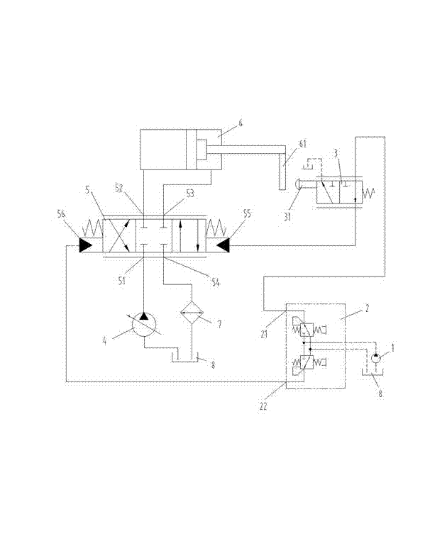
[0012] Such as figure 1 As shown, the present invention includes a pilot pump 1, a pilot control valve 2, a limit control valve 3, a main pump 4, a main hydraulic control valve 5 and a boom cylinder 6, and the limit control valve 3 is a two-position three-way stroke slide valve , the output port of the pilot pump 1 communicates with the oil inlet of the pilot control valve 2, the first oil outlet 21 of the pilot control valve 2 communicates with the first hydraulic control port 55 of the main hydraulic control valve 5 through the limit control valve 3, and the pilot control valve 2 The second oil outlet 22 communicates with the second hydraulic control port 56 of the main hydraulic control valve 5, the output end of the main pump 4 directly communicates with the oil inlet 51 of the main hydraulic control valve 5, and the first outlet of the main hydraulic control valve ...


PUM


Abstract

The invention discloses a hydraulic circuit capable of accurately controlling a lifting height of a movable arm of an excavator. The hydraulic circuit comprises a pilot-operated pump, a pilot-operated control valve, a limiting control valve, a main pump, a main hydraulic control valve and a movable arm oil cylinder, wherein an output end of the pilot-operated pump is communicated with an oil inlet of the pilot-operated control valve; a first oil outlet of the pilot-operated control valve is communicated with a first hydraulic control opening of the main hydraulic control valve through a limiting control valve; a second oil outlet of the pilot-operated control valve is communicated with a second hydraulic control opening of the main hydraulic control valve; an output end of the main pump is communicated with an oil inlet of the main hydraulic control valve; two oil outlets of the main hydraulic control valve are respectively communicated to front and rear cavities of the movable arm oil cylinder; a limiting pressing plate is arranged at one side of a piston rod of the movable arm oil cylinder and corresponds to the position of a contact of the limiting control valve; and when the movable arm is lifted to the pre-set height, the limiting pressing plate is pressed on the contact of the limiting control valve to lock the movable arm. The movable arm of the excavator is accurately positioned, the labor intensity is reduced and the working efficiency of the excavator is improved.

Description

technical field [0001] The invention relates to an excavator hydraulic circuit, in particular to an excavator arm lifting hydraulic circuit, which belongs to the technical field of engineering machinery. Background technique [0002] The boom is an important part of the working device of the hydraulic excavator. The hydraulic excavator controls the swing of the boom and the rotation of the bucket through the hydraulic circuit to complete the excavation. With the improvement of people's functional requirements for excavators, it is necessary to replace the extended boom for the excavator, or to complete the excavation within a limited space, but the lifting height of the existing excavator boom is mainly controlled manually by the operator visually. When reaching the predetermined height, the manual control makes the boom cylinder slow down the expansion and contraction speed, so that it slowly rises to the predetermined height. Due to the visual error, it is impossible to a...

Claims


Application Information

Patent Timeline
Patent Type & Authority Applications(China)
IPC IPC(8): E02F3/43
Inventor 牛选平高剑英魏兴虎薛传林孙永建
Owner 中外合资沃得重工(中国)有限公司
Learn More