
Spinning winder

A winding machine and spinning technology, which is applied in the direction of textiles and papermaking, conveying filamentous materials, and clustering of newly extruded filaments. The effect of the bend angle

Active Publication Date: 2013-01-23
TMT MACHINERY INC
View PDF5 Cites 7 Cited by
  • Summary
  • Abstract
  • Description
  • Claims
  • Application Information

AI Technical Summary

Problems solved by technology

Therefore, in the case of a thin thread, the force acting on the thread from the distribution thread guide is large, and the thread may be greatly damaged.

Method used


Image

  • Spinning winder
  • Spinning winder
  • Spinning winder

Examples


Embodiment

[0057] then use Image 6 Examples of the present invention will be described. Image 6 It is a diagram showing test results of yarn physical properties measurement of the yarn 10 performed downstream of the fulcrum guide 13 when the fulcrum guide 13 of various radii R distributes the spun yarn Y sent from the godet roll 12 . Wherein, the so-called physical property of the wire refers to the ratio of the tensile stress when the wire 10 is broken when the wire 10 is stretched and bent to the tensile stress when the wire 10 is broken when the wire 10 is not bent, and the higher the value, It means that the damage to the wire 10 at the fulcrum guide 13 is smaller. and, Image 6 It shows that the silk thread 10 is a multifilament of polyester material FDY, 150de, the winding angle θ of the silk thread 10 at the fulcrum guide 13 is 30°, the walking speed of the silk thread 10 is 4800m / min, and the ratio of the fulcrum guide 13 Experimental results when the yarn tension on the ups...


PUM

PropertyMeasurementUnit
Bending angleaaaaaaaaaa

Abstract

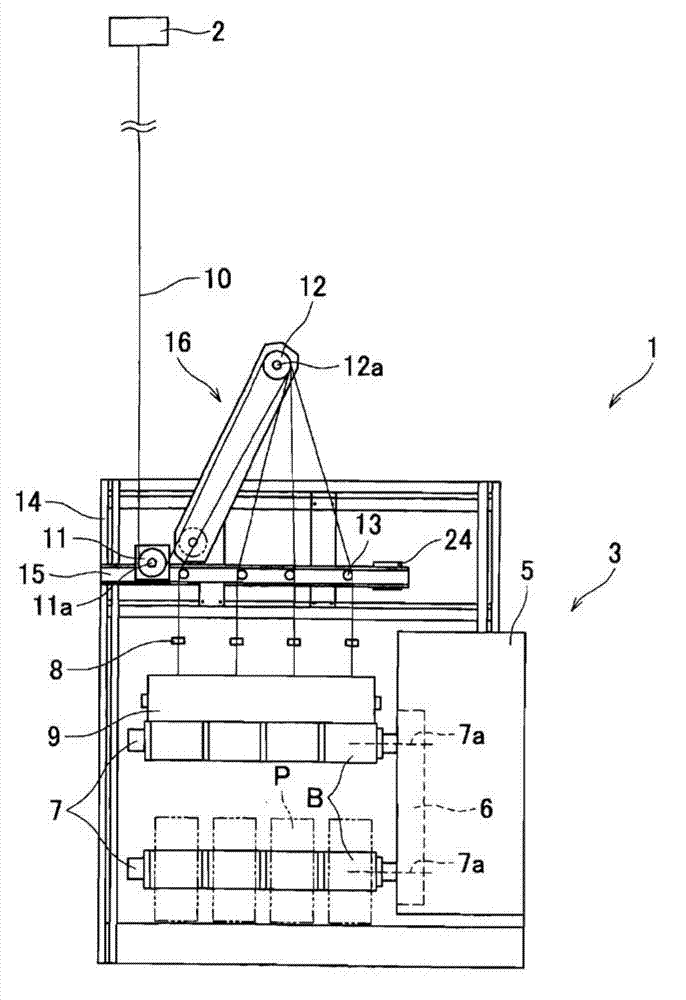
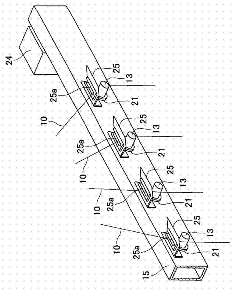
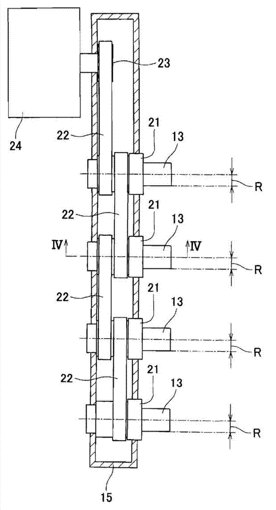
Damage on yarns is restrained while allowing the bending angles of the yarns at distribution guides by which the yarns spun out from a spinning unit are distributed to be large. Yarns 10 serially spun out and supplied from a spinning machine are conveyed to a winding unit below by two godet rollers, and in a winding unit the yarns 10 are distributed by fulcrum guides 13 and then wound onto bobbins attached to a bobbin holder. Each fulcrum guide 13 is a column having a radius of not shorter than 3mm and not longer than 8mm, and the yarn 10 is threaded on the outer circumference of the fulcrum guide 13. By rotating the fulcrum guide 13, the sliding position between the fulcrum guide 13 and the yarn 10 is changed. Furthermore, the movement of the yarn 10 threaded on the fulcrum guide 13 is restrained in the axial directions of the fulcrum guide 13, because the yarn 10 is arranged to pass through a slit 25a made through a restraining guide 25 which is provided above the fulcrum guide 13.

Description

technical field [0001] The present invention relates to a spinning winder for winding a plurality of yarns sent out from a spinning section onto a plurality of bobbins. Background technique [0002] In the spinning winder described in Patent Document 1, a plurality of yarns sent out from the spinning machine are distributed one by one to a plurality of distribution guides arranged in the axial direction of the bobbin holder via a pair of godet rollers. device (traversing fulcrum wire guide). The yarn distributed to the distribution guide is bent on the distribution guide, delivered to the bobbin mounted on the bobbin holder, and wound onto the bobbin. [0003] Here, in the spinning winder described in Patent Document 1, since the yarn is bent on the distribution guide as described above, if the bending angle (winding angle) of the yarn is large, the surface of the yarn is applied from the distribution guide. The pressure is high, and the silk thread is greatly damaged. On...

Claims


Application Information

Patent Timeline
IPC IPC(8): D01D7/00
CPCB65H54/20B65H67/048B65H67/056B65H2701/3132B65H2601/121B65H51/06B65H67/052B65H57/14
Inventor 桥本欣三岸根章典鸟居裕矢
Owner TMT MACHINERY INC
Learn More