contactless data transmission device
A data transmission device, non-contact technology, applied in transmission systems, near-field transmission systems, electrical components, etc., can solve problems such as high concentricity, practical application limitations, and harsh use conditions, so as to improve service life and mechanical coordination Simple, mechanically wear-free effect
- Summary
- Abstract
- Description
- Claims
- Application Information
AI Technical Summary
Problems solved by technology
Method used
Image
Examples
Embodiment 1
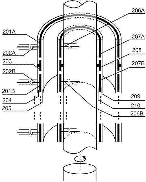
[0023] The non-contact data transmission device is characterized in that it includes a shaper 101, a phase separator 102, an electric field coupling loop 103, a first charge amplifier 104A, a second charge amplifier 104B, a subtractor 105, a positive comparator 106, a negative The comparator 107 and the R-S flip-flop 108, the input signal is sent to the input terminal of the phase separator 102 after the input signal is shaped by the shaper 101, and after the phase separator 102, two D+ data line signals and D - Data line signals, wherein the D+ data line signal and the D− data line signal are sent to the first charge amplifier 104A and the second charge amplifier 104B through the electric field coupling loop 103 .
Embodiment 2
[0025] Refer to attached figure 1 , a rotary contactless data transmission device, including a shaper 101, a phase separator 102, an electric field coupling loop 103, a first charge amplifier 104A, a second charge amplifier 104B, a subtractor 105, a positive comparator 106, and a negative comparator 107 and R-S flip-flop 108, the input signal is sent to the input terminal of the phase separator 102 after the input signal is shaped by the shaper 101, and after the phase separator 102, two D+ data line signals and D- data lines with a phase difference of 180 degrees are obtained line signal, wherein the D+ data line signal and the D- data line signal are sent to the charge amplifier 104A and the charge amplifier 104B through the electric field coupling loop 103; the signals output by the first charge amplifier 104A and the second charge amplifier 104B are sent to the subtractor 105, Subtractor 105 outputs the difference between the two signals; at each input signal 0 / 1 jump mome...
PUM
 Abstract
Description
Claims
Application Information
 - R&D Engineer
- R&D Manager
- IP Professional
- Industry Leading Data Capabilities
- Powerful AI technology
- Patent DNA Extraction
Browse by: Latest US Patents, China's latest patents, Technical Efficacy Thesaurus, Application Domain, Technology Topic, Popular Technical Reports.
© 2024 PatSnap. All rights reserved.Legal|Privacy policy|Modern Slavery Act Transparency Statement|Sitemap|About US| Contact US: help@patsnap.com


