Bi-stable three-way valve

A three-way valve and bistable technology, applied in the field of three-way valve, can solve the problems of power consumption, unsafe and reliable, high manufacturing cost, and achieve the effects of energy saving, stable work, safety and reliability

Inactive Publication Date: 2013-01-16
NINGBO RAVO IND GRP CO LTD
View PDF5 Cites 2 Cited by
  • Summary
  • Abstract
  • Description
  • Claims
  • Application Information

AI Technical Summary

Problems solved by technology

[0002] The current three-way valve is a gradual change when changing the state, and its state change cannot be jumped from one state to another in a jumping way, such as the circulating water supply between the water storage tank and the bottled water used in the water boiler In the system, the conversion of the three-way valve is gradually converted. Due to improper operation, the upper and lower water inlets are often open, which makes the circulating water supply system invalid.
For this reason, double valves are often used in combination or three-way solenoid valves are used instead, and the use of solenoid valves in circulating water supply systems not only has high manufacturing costs, consumes electric energy, and is not safe and reliable.

Method used


Image

  • Bi-stable three-way valve
  • Bi-stable three-way valve
  • Bi-stable three-way valve

Examples


Embodiment Construction

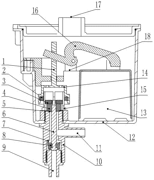
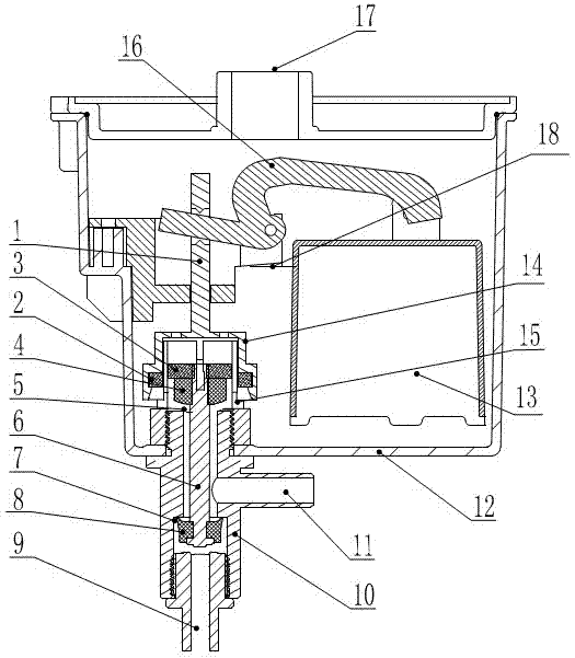
[0013] The structure and working state of the present invention will be further described below in conjunction with the accompanying drawings.

[0014] Such as Figure 1~2 As shown, the float 13 located in the water tank 12 and the magnetic ring assembly located on one side of the float 13, the three-way valve body 10 that is located under the magnetic ring assembly and communicates with the water tank 12, and the three-way valve body 10 that is located in the three-way valve body 10 The three-way valve core 6, the upper and lower ends of the three-way valve core 6 are nested with the upper valve plug 4 and the lower valve plug 8, and the side wall of the three-way valve body 10 is provided with a water outlet 11, an upper water inlet 5 and a lower water inlet 7, and the three-way The upper end of the valve core 6 and the upper valve plug 4 are fixedly connected with the lower end of the inner magnetic ring 3 of the magnetic ring assembly. The outer magnetic ring 2 of the mag...


PUM


Abstract

A bi-stable three-way valve comprises a water tank, a buoy and a three-way valve. The buoy is arranged in the water tank, the three-way valve is communicated with the water tank, a magnetic ring assembly connected with the upper end of a three-way valve spool is further disposed in the water tank, and comprises an outer magnetic ring and an inner magnetic ring, the outer magnetic ring is arranged on the inner wall of a cylinder, the inner magnetic ring is arranged in the cylinder, the inner magnetic ring and the outer magnetic ring are arranged in a like polarity manner, a draw bar is connected to the upper end of the magnetic ring assembly, moves up and down along with ascending and descending of the buoy, and pulls the outer magnetic ring or the inner magnetic ring to generate magnetic repulsive force, the three-way valve spool is driven by the magnetic repulsive force to move up and down in the three-way valve, and valve plugs which are respectively arranged at the upper end and the lower end of the three-way valve spool simultaneously open or close an upper water inlet and a lower water inlet. Buoyancy of the buoy in the existing water tank is converted into the magnetic repulsive force of the inner magnetic ring and the outer magnetic ring, and the magnetic repulsive force is further converted into force for driving the three-way valve spool to move up and down in the valve, so that the valve plugs which are respectively arranged at the upper end and the lower end of the valve spool can open the upper water inlet and close the lower water inlet simultaneously or close the upper water inlet and open the lower water inlet simultaneously when acting, stable, safe and reliable operation of a circulating water supply system of a water boiler is kept, and energy consumption is reduced.

Description

technical field [0001] The invention relates to a three-way valve, which is a bistable three-way valve driven by magnetic repulsion. Background technique [0002] The current three-way valve is a gradual change when changing the state, and its state change cannot be jumped from one state to another in a jumping way, such as the circulating water supply between the water storage tank and the bottled water used in the water boiler In the system, the conversion of the three-way valve is gradually converted. Due to improper operation, the upper and lower water inlets are often open, which makes the circulating water supply system invalid. For this reason, double valves are often used in combination or three-way solenoid valves are used instead, and the use of solenoid valves in circulating water supply systems not only has high manufacturing costs, consumes electric energy, and is not safe and reliable. Contents of the invention [0003] The technical problem to be solved by ...

Claims


Application Information

Patent Timeline
Patent Type & Authority Applications(China)
IPC IPC(8): F16K31/08F16K31/20F16K11/04
Inventor 杨宁恩商加瑞
Owner NINGBO RAVO IND GRP CO LTD
Why Eureka
Try Eureka