
Turbine rotor blade and gas turbine with same

A turbine rotor and blade technology, which is applied to the supporting elements of blades, mechanical equipment, engine elements, etc., can solve the problems of insignificant vibration reduction effect, large blade flow loss, and large blade vibration, so as to improve turbine efficiency and improve gas Flow, the effect of suppressing radial deformation

Active Publication Date: 2013-01-16
HUNAN HANGXIANG GAS TURBINE
View PDF8 Cites 7 Cited by
  • Summary
  • Abstract
  • Description
  • Claims
  • Application Information

AI Technical Summary

Problems solved by technology

[0006] The purpose of the present invention is to provide a turbine rotor blade and a gas turbine with it, so as to solve the technical problem of large flow loss of blades with shrouds in the prior art; obvious technical problem

Method used


Image

  • Turbine rotor blade and gas turbine with same
  • Turbine rotor blade and gas turbine with same
  • Turbine rotor blade and gas turbine with same

Examples


Embodiment Construction

[0024] It should be noted that, in the case of no conflict, the embodiments in the present application and the features in the embodiments can be combined with each other. The present invention will be described in detail below with reference to the accompanying drawings and examples.

[0025] It should be noted that the circumferential and axial directions mentioned in the present invention refer to the circumferential and axial directions of the blisk after the blades are assembled.

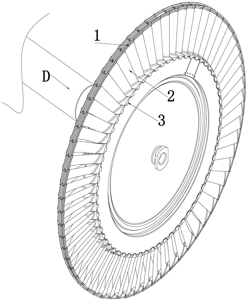
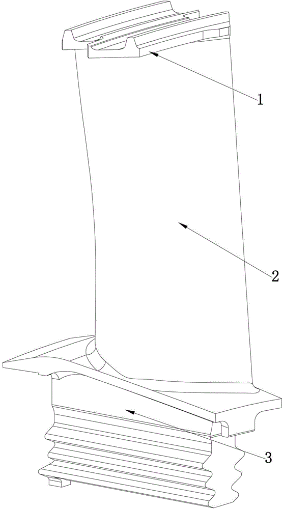
[0026] Such as figure 1 and figure 2 As shown, the turbine rotor blade in the embodiment of the present invention includes a shroud 1, a blade body 2 and a tenon 3; figure 1 and Figure 5 The direction indicated by the arrow D in the flow into the turbine rotor blade.

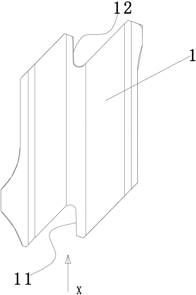
[0027] Such as image 3 As shown, the shroud 1 of the turbine rotor blade in the embodiment of the present invention includes a first pre-twisted contact surface 11 and a second pre-twisted contact surface 12 . The first ...


PUM


Abstract

The invention provides a turbine rotor blade and a gas turbine with the same. The turbine rotor blade comprises a shroud, a blade body and a tenon, the shroud comprises a first pre-twist contact surface and a second pre-twist contact surface, wherein the first pre-twist contact surface is peripherally arranged at a first peripheral end of the shroud, and the second second pre-twist contact surface is peripherally arranged at a second peripheral end of the shroud. Arrangement of the first pre-twist contact surface and the second pre-twist contact surface includes that after a plurality of turbine rotor blades are assembled, the second pre-twist contact surface of each turbine rotor blade is matched with the first pre-twist contact surface of each adjacent turbine rotor blade in an extrusion manner, so that the shrouds of each two adjacent turbine rotor blades jointly generate a pre-twist angle by using a blade stacking shaft as the axis. According to the technical scheme, the shrouds of each two adjacent turbine rotor blades have the pre-twist moment with the direction opposite to that of the moment generated by gas impact force, so that twist and bending deformation of the blades in work can be effectively inhibited, and flow blade profile loss is reduced.

Description

technical field [0001] The invention relates to the field of power machinery, in particular to a turbine rotor blade and a gas turbine equipped with it. Background technique [0002] Turbine rotor blades are important parts that convert the energy of high-temperature gas into mechanical work of the rotor. When working, it is not only surrounded by constantly changing high-temperature gas, but also bears the huge centrifugal force, gas force and vibration load generated by high-speed rotation. Therefore, the working conditions of the turbine rotor blades are very harsh, which determines the life of the gas turbine. one of the main parts. Therefore, it is particularly important to improve the efficiency, reliability and stability of turbine rotor blades. The complex flow in the tip clearance of rotor blades is one of the important factors affecting the turbine efficiency of gas turbines, and researchers have made great efforts to reduce the flow loss in the tip clearance. T...

Claims


Application Information

Patent Timeline
IPC IPC(8): F01D5/14F01D5/16
Inventor 杨家礼张亿力李久山黄舜阳诚武刘秀芳季星星
Owner HUNAN HANGXIANG GAS TURBINE
Learn More