Stable hydraulic wheel puller

A pulley, stable technology, applied in the field of pulley pullers, can solve the problems of uneven force, waste of resources, pull out the edge of the pulley, etc., to achieve uniform focus, improve work efficiency, and increase the force area. Effect

Inactive Publication Date: 2013-01-16
常州市诚万建设工程有限公司
View PDF0 Cites 1 Cited by
  • Summary
  • Abstract
  • Description
  • Claims
  • Application Information

AI Technical Summary

Problems solved by technology

[0002] The belt pulley of the motor needs to be replaced when it breaks down, which requires the pulley to be pulled out from the motor shaft. The disadvantage of the pulley is that the three claws are easy to pull out during operation, and due to uneven force, the edge of the pulley is often pulled out, causing damage and scrapping, which not only wastes resources, increases costs, but also affects production efficiency

Method used


Image

  • Stable hydraulic wheel puller
  • Stable hydraulic wheel puller

Examples


Embodiment Construction

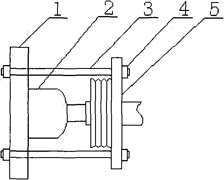
[0012] Such as figure 1 It is a schematic diagram of the present invention. A stable hydraulic puller includes a base 1, a jack 2, a screw 3, a nut 4, and a puller plate 5. The jack 2 is connected to the base 1 as a whole, and the puller plate 5 passes through the screw 3 is connected to the base 1, and the puller plate 5 is a lock ring structure.

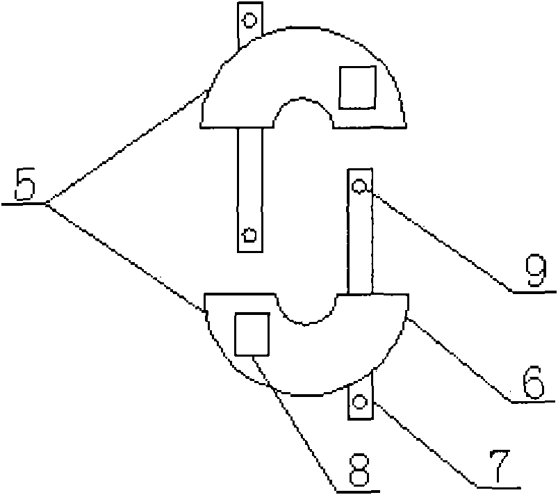
[0013] Such as figure 2 It is a schematic diagram of the puller plate of the present invention. The puller plate 5 is composed of two lock plates 6. Each lock plate 6 is provided with a pin 7 and a shaft sleeve 8. Each pin 7 is provided with a screw hole 9 at both ends.

[0014] When in use, put the two lock plates 6 on the pulley, so that the pin 7 on each lock plate 6 is inserted into the other shaft sleeve 8, thereby locking the pulley; and then insert the screw 3 into the screw hole 9. Tighten the nut 4 and connect it with the base 1 as a whole; then use the jack 2 to pull out the pulley.


PUM


Abstract

The invention relates to the field of a belt pulley pulling device, in particular to a stable hydraulic wheel puller. The stable hydraulic wheel puller comprises a base, a jack, a screw, a nut and a wheel pulling plate. The jack is connected with the base integrally, the wheel pulling plate is connected with the base through the screw, and the wheel pulling plate adopts a lock ring structure. The wheel pulling plate is formed by combining two locking pieces. Each locking piece is provided with a pin shaft and a shaft sleeve. Two crewed holes are formed in both ends of each pin shaft respectively. The wheel puller is arranged on the back of the belt pulley in a sleeving manner, so that the stress area of the belt pulley is enhanced; and the origin of force is uniform, and the belt pulley does not fall off and is not damaged, so that the work efficiency is greatly improved.

Description

Technical field [0001] The invention relates to the field of pulley pulling devices, in particular to a stable hydraulic puller. Background technique [0002] When the motor's pulley fails, it needs to be replaced. This requires pulling out the pulley from the motor shaft. The existing puller is fixed with three claws and the center is a screw support. Screw in the screw and pull out the pulley. The disadvantage of the wheel device is that the three claws are easy to pull out during operation, and due to uneven force, the edges of the pulley are often pulled out, causing damage and scrap, which not only wastes resources, increases costs, but also affects production efficiency. Summary of the invention [0003] In order to overcome the shortcomings of the existing pulley pullers that are easy to fall off and have great destructiveness, the present invention provides a stable hydraulic puller. [0004] The technical solution adopted by the present invention to solve its technical pro...

Claims


Application Information

Patent Timeline
IPC IPC(8): B23P19/027
Inventor 李岳方
Owner 常州市诚万建设工程有限公司
Why Eureka
Try Eureka