Pitch-variable clamp for wafer replacing

A variable pitch and fixture technology, applied in sustainable manufacturing/processing, electrical components, climate sustainability, etc., can solve problems such as high labor intensity, low efficiency, uncontrollable fragmentation rate, etc.

Active Publication Date: 2013-01-09
ROBOTECHN INTELLIGENT TECH CO LTD
View PDF5 Cites 0 Cited by
  • Summary
  • Abstract
  • Description
  • Claims
  • Application Information

AI Technical Summary

Problems solved by technology

This method is inefficient, labor intensive, and the fragmentation rate is uncontrollable

Method used


Image

  • Pitch-variable clamp for wafer replacing
  • Pitch-variable clamp for wafer replacing
  • Pitch-variable clamp for wafer replacing

Examples


Embodiment 1

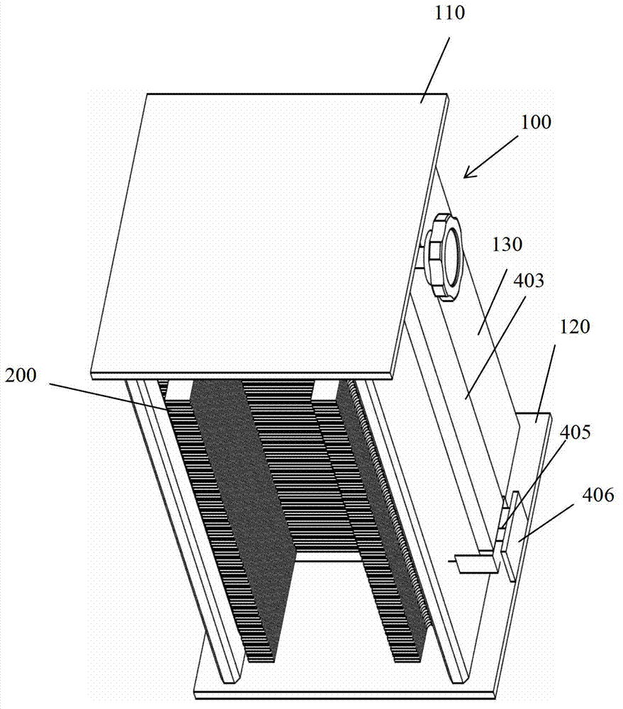
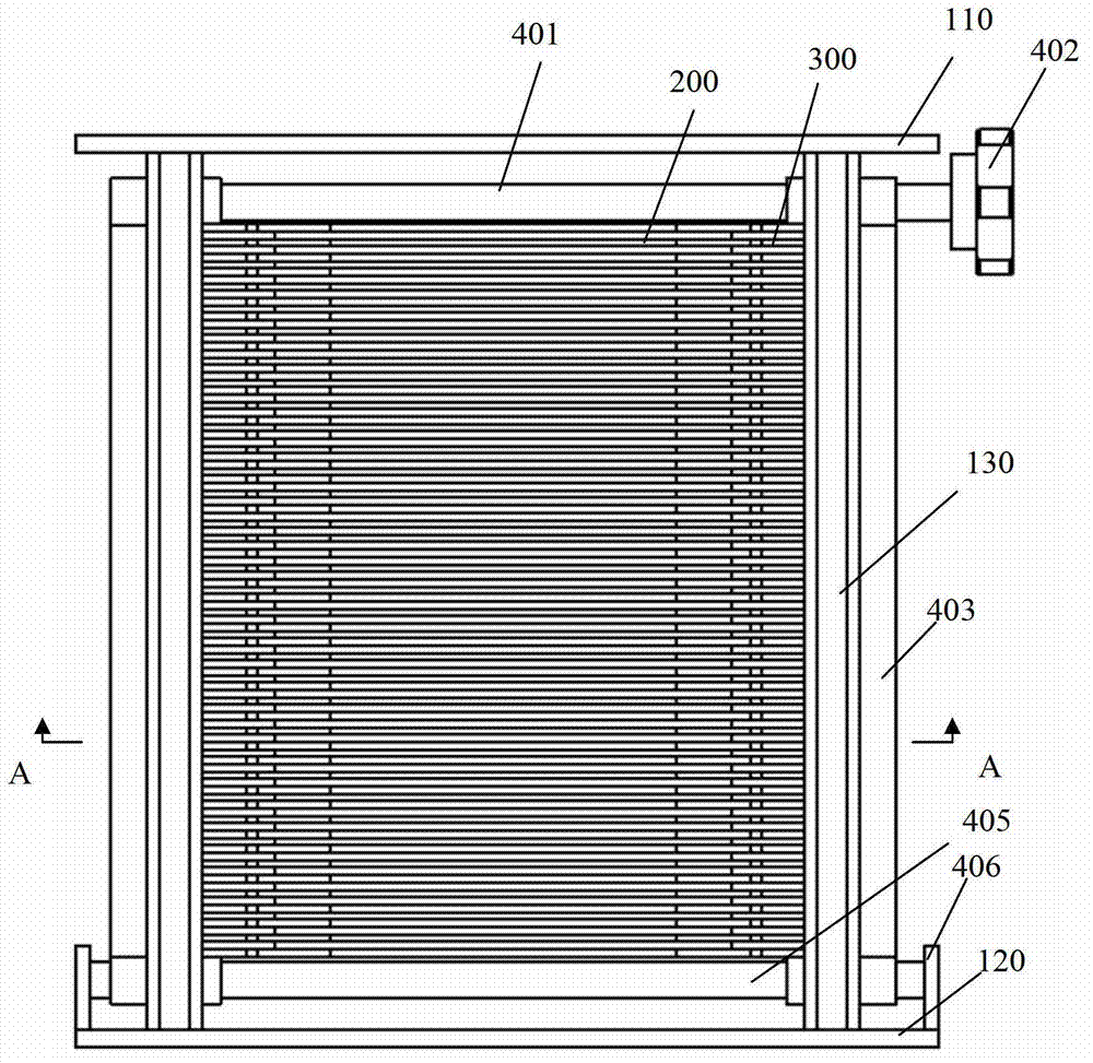
[0025] Such as figure 1 , figure 2 , image 3 As shown, the variable pitch jig for film rewinding of the present invention includes a frame 100, a multi-layer silicon wafer resting plate 200, spacers 300 and a driving mechanism.

[0026] The frame 100 is surrounded by a top plate 110 , a bottom plate 120 and two side plates 130 separated on the left and right sides. Openings are formed at the front and back of the frame 100 to allow silicon wafers to enter and exit.

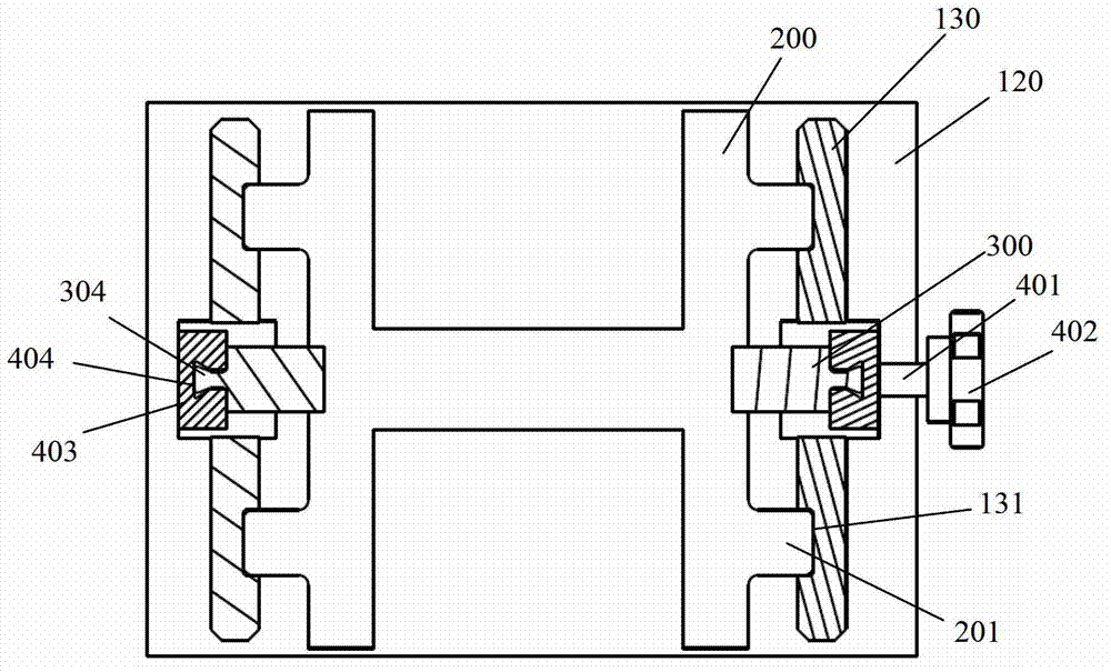
[0027] Such as Figure 5 As shown, the inner surface of the side plate 130 has vertically extending slide grooves 131 on both sides, and has a vertically extending strip-shaped gap 132 in the middle.

[0028] Figure 6 As shown, the thickness of each silicon wafer resting plate 200 is 2 mm, and two protruding sliders 201 are respectively provided at both ends. combine image 3 As shown, when the protruding slider 201 is assembled, it is located in the slide groove 131 of the side plate 130 . In this way, ...

Embodiment 2

[0037] Such as Figure 10 , 11 , 12, the difference between this embodiment and embodiment 1 is that: the spacer 300 is circular and has a square hole 305 in the middle. The driving mechanism is two driving rods 501 with a square cross-section arranged on both sides of the silicon wafer resting plate, and each driving rod 501 passes through the clamping holes 305 of all spacers 300 on the same side in turn. A synchronous belt (not shown) is installed between the two driving rods 501 . Other structures are the same as in Embodiment 1. In this embodiment, the thick portion 302 of the spacer 300 is driven to be inserted into or pulled out of the gap between the silicon wafer resting racks by rotating the lever 501 . A timing belt is installed between the two driving rods 501 so that the driving rod 501 can drive the spacer 300 to rotate at the same time, ensuring that the thick part 302 of the spacer 300 on both sides can be inserted or pulled out between the silicon wafer res...


PUM


Abstract

The invention discloses a pitch-variable champ for wafer replacing. The pitch-variable clamp comprises a top plate, a bottom plate, a frame enclosed by two lateral plates and multilayer silicon wafer placing plates capable of sliding vertically along the inner surfaces of the two lateral plates in the frame, wherein gaps are arranged among the multilayer silicon wafer placing plates, and a space gasket is respectively arranged at two ends of each layer of gap; the front ends of the gaps are thin portions, the tail ends of the gaps are thick portions, the middle portions of the gaps are gradually-changed inclined surfaces, and the thin portions are inserted into the gaps. The pitch-variable clamp further comprises driving mechanisms driving the space gaskets so as to enable the thick portions to enter or quit from the spaces. The pitch-variable clamp for wafer replacing can fast change the distance among the silicon wafers, so that wafer replacing between two different pitch carriers can be achieved fast, stably and conveniently.

Description

technical field [0001] The invention belongs to the technical field of photovoltaic silicon wafer production equipment, and in particular relates to a variable pitch clamp for rewinding wafers in the photovoltaic silicon wafer production equipment. Background technique [0002] In order to improve the production capacity of photovoltaic silicon wafer diffusion process, it is the most convenient and widely used method to reduce the pitch of the silicon wafer carrier quartz boat (for example, from 4.76mm to 4.05mm) without changing the main equipment of the process. Before the diffusion process, the silicon wafer needs to be poured into the quartz boat from another carrier flower basket; after the process is completed, the silicon wafer needs to be poured into the flower basket from the quartz boat to transfer the silicon wafer to the next process. Because the transfer of silicon wafers between processes uses a flower basket of 4.76mm, when the pitch of the quartz boat is 4.76...

Claims


Application Information

Patent Timeline
Patent Type & Authority Applications(China)
IPC IPC(8): H01L21/687H01L31/18
CPCY02P70/50
Inventor 朱绍明戴军
Owner ROBOTECHN INTELLIGENT TECH CO LTD
Why Eureka
Try Eureka