Steadily operating variable pitch clamp

A technology with stable operation and variable pitch, applied in sustainable manufacturing/processing, electrical components, climate sustainability, etc., can solve the problems of high labor intensity, low efficiency, uncontrollable fragmentation rate, etc.

Active Publication Date: 2014-11-26
ROBOTECHN INTELLIGENT TECH CO LTD
View PDF1 Cites 0 Cited by
  • Summary
  • Abstract
  • Description
  • Claims
  • Application Information

AI Technical Summary

Problems solved by technology

This method is inefficient, labor intensive, and the fragmentation rate is uncontrollable

Method used


Image

  • Steadily operating variable pitch clamp
  • Steadily operating variable pitch clamp
  • Steadily operating variable pitch clamp

Examples


Embodiment Construction

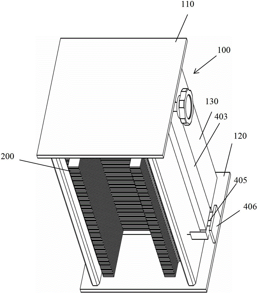
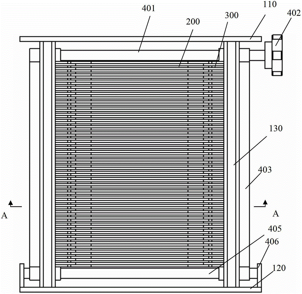
[0023] Such as figure 1 , 2 As shown in , 3, the variable pitch fixture with stable operation of the present invention includes a frame 100, a multi-layer silicon wafer resting plate 200, a spacer 300 and a driving mechanism.

[0024] The frame 100 is surrounded by a top plate 110 , a bottom plate 120 and two side plates 130 separated on the left and right sides. Openings are formed at the front and back of the frame 100 to allow silicon wafers to enter and exit.

[0025] Such as Figure 5 As shown, the inner surface of the side plate 130 has vertically extending slide grooves 131 on both sides, and has a vertically extending strip-shaped gap 132 in the middle.

[0026] Such as Figure 6 As shown, the thickness of each silicon wafer resting plate 200 is 2 mm, and two protruding sliders 201 are respectively provided at both ends. combine image 3 As shown, when the protruding slider 201 is assembled, it is located in the slide groove 131 of the side plate 130 . In this wa...


PUM


Abstract

The invention discloses a steadily operating variable pitch clamp. The steadily operating variable pitch clamp comprises a top plate, a base plate, a frame surrounded by two side plates, and multiple layers of silicon wafer shelves which are located in the frame and can sliding up and down along the inner surfaces of the two side plates. The multiple layers of silicon wafer shelves are spaced with gaps, and two ends of the gap at each layer both are provided with an interval gasket; the head end of the interval gasket is a thin part while the tail end thereof is a thick part and the middle part thereof is a gradually changing inclined plane, the thin part is inserted into the gap, all the interval gaskets are equal in total length, the length of the gradually changing inclined plane is also equal, and the interval gaskets from the bottom layer to the top layer vary according to the following law: the length of the thin part increases gradually, and the length of the thick part reduces gradually; moreover, the steadily operating variable pitch clamp further comprises a driving mechanism for driving all the interval gaskets to enable the thick parts simultaneously enter into or exit from the gaps. The steadily operating variable pitch clamp provided by the invention can quickly change the interval between the silicon wafers, thereby quickly, steadily and conveniently dumping the silicon wafers between two carriers which have different pitches.

Description

technical field [0001] The invention belongs to the technical field of photovoltaic silicon wafer production equipment, and in particular relates to a variable pitch fixture with stable operation in the photovoltaic silicon wafer production equipment. Background technique [0002] In order to improve the production capacity of photovoltaic silicon wafer diffusion process, it is the most convenient and widely used method to reduce the pitch of the silicon wafer carrier quartz boat (for example, from 4.76mm to 4.05mm) without changing the main equipment of the process. Before the diffusion process, the silicon wafer needs to be poured into the quartz boat from another carrier flower basket; after the process is completed, the silicon wafer needs to be poured into the flower basket from the quartz boat to transfer the silicon wafer to the next process. Because the transfer of silicon wafers between processes uses a flower basket of 4.76mm, when the pitch of the quartz boat is 4...

Claims


Application Information

Patent Timeline
Patent Type & Authority Patents(China)
IPC IPC(8): H01L21/687H01L31/18
CPCY02P70/50
Inventor 朱绍明戴军
Owner ROBOTECHN INTELLIGENT TECH CO LTD
Why Eureka
Try Eureka