
Ultralow temperature vacuum insulation quick connector and production method thereof

A technology of vacuum insulation and connectors, which is applied in the direction of heat preservation, couplings, heat exchange equipment, etc. It can solve the problems of slow installation of connection methods, inability to open quickly, and unsafety, so as to prevent malfunctions and fast and safe connections and the effect of separation

Inactive Publication Date: 2013-01-09
李宏
View PDF10 Cites 6 Cited by
  • Summary
  • Abstract
  • Description
  • Claims
  • Application Information

AI Technical Summary

Problems solved by technology

[0002] With the advent of the adjustment of the global energy structure, the construction of domestic liquefied natural gas (LNG) receiving stations, loading and unloading stations, and vehicle and ship filling stations is advancing by leaps and bounds. It has become a key issue to realize fast and safe connections in the process of LNG receiving, unloading and filling. The existing connection methods are slow to install or unsafe, and ultra-low temperature fluids (LNG, liquid nitrogen, liquid oxygen, liquid hydrogen, etc.) The loading and unloading flange interface cannot be opened quickly due to ice formation

Method used


Image

  • Ultralow temperature vacuum insulation quick connector and production method thereof
  • Ultralow temperature vacuum insulation quick connector and production method thereof
  • Ultralow temperature vacuum insulation quick connector and production method thereof

Examples


Embodiment Construction

[0018] The preferred embodiments of the present invention are given below in conjunction with the accompanying drawings to describe the technical solution of the present invention in detail.

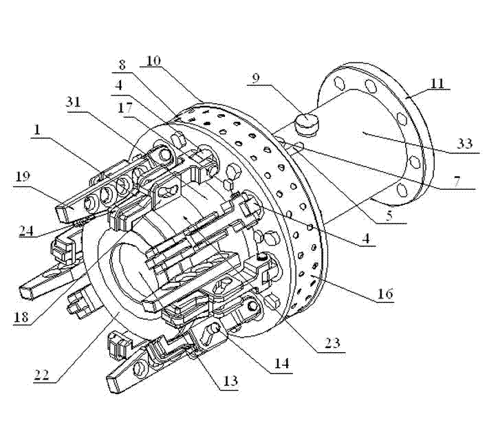
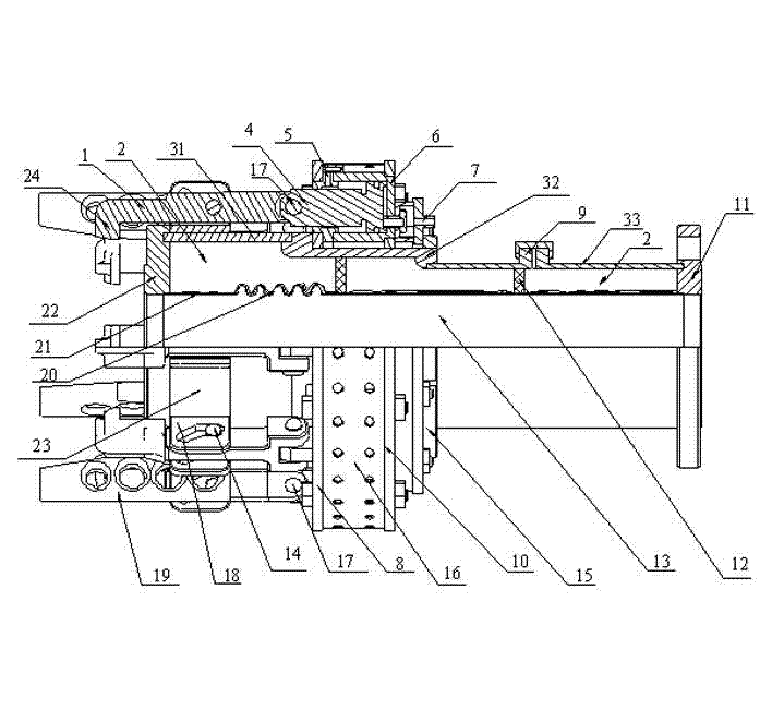
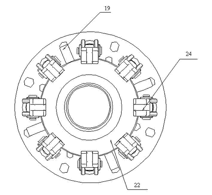
[0019] Such as Figure 1 to Figure 3 As shown, the ultra-low temperature vacuum insulation quick connector of the present invention includes a pull rod 1, a vacuum chamber 2, a first outer tube 31, a second outer tube 32, a third outer tube 33, a piston rod 4, a first oil port 5, an oil cylinder 6, The second oil port 7, the first oil cylinder splint 8, the vacuum port 9, the second oil cylinder splint 10, the connecting flange 11, the supporting ring 12, the flow channel 13, the guide shaft 14, the fixing ring 15, the protective cover 16, the connecting shaft 17 , guide plate 18, guide rod 19, corrugated inner tube 20, multi-layer insulation layer 21, butt joint flange 22, ring-type rotary body 23, claw 24, pull rod 1 and claw 24 are integrally formed, and pull rod 1 passes through the ...


PUM


Abstract

The invention discloses an ultralow temperature vacuum insulation quick connector and a production method thereof. The connector comprises a pull rod, a vacuum cavity, a first outer pipe, a second outer pipe, a third outer pipe, a piston rod, a first oil orifice, a cylinder and the like. The pull rod is integrated with a jaw. The pull rod can be connected with a piston pin through a connecting shaft. The vacuum cavity is located among the first outer pipe, the second outer pipe, the third outer pipe and an inner corrugated pipe. The first oil orifice is located at the front end of the cylinder. A second oil orifice is located at the rear of the cylinder. The cylinder is connected with the piston rod. A vacuum opening is connected with the third outer pipe and communicated with the vacuum cavity. A counter flange and a connecting flange are welded with two ends of the inner corrugated pipe respectively. A support ring is located in the vacuum cavity between the inner corrugated pipe and the third outer pipe. A guide plate and a guide rod are welded to an annular rotator and fixed on the first outer pipe. By the ultralow temperature vacuum insulation quick connector, fast and safe connection and separation of a pipeline or a loading arm with a tank-truck or a LNG (liquefied natural gas) ship during ultralow-temperature liquid loading and unloading are achieved.

Description

technical field [0001] The invention relates to a connector, in particular to an ultra-low temperature vacuum heat insulation quick connector and a manufacturing method thereof. Background technique [0002] With the advent of the adjustment of the global energy structure, the construction of domestic liquefied natural gas (LNG) receiving stations, loading and unloading stations, and vehicle and ship filling stations is advancing by leaps and bounds. It has become a key issue to realize fast and safe connections in the process of LNG receiving, unloading and filling. The existing connection methods are slow to install or unsafe, and ultra-low temperature fluids (LNG, liquid nitrogen, liquid oxygen, liquid hydrogen, etc.) The loading and unloading flange interface cannot be opened quickly due to ice formation. Contents of the invention [0003] The technical problem to be solved by the present invention is to provide an ultra-low temperature vacuum insulated quick connect...

Claims


Application Information

Patent Timeline
IPC IPC(8): F16L37/12F16L59/18
Inventor 不公告发明人
Owner 李宏
Learn More